Because RFL™ and Hubbell® have a policy of continuous product improvement, we reserve the right to change designs and specifications without notice.
2.4 MULTIPLEXER, FRONT-PANEL SWITCHES, INDICATORS, AND
JACKS
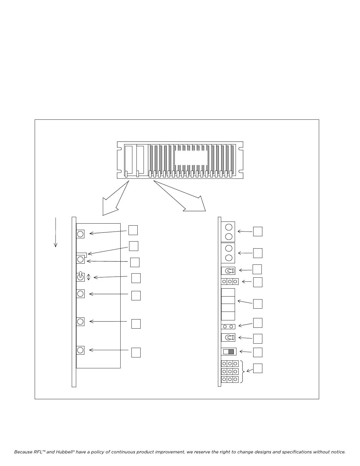
Figure 2-19 is a front view of the IMUX 2000 terminal multiplexer with its front door open. A
drop/insert multiplexer will look the same, except for the addition of a second CM4 Common Module.
The main power supply module and the E1 common module are expanded to show the location of all
front panel switches, indicators, and jacks. Functional descriptions of these switches, indicators, and
jacks appear in Tables 2-4 through 2-13. The numbers in the Item columns of these tables refer to the
numbers in the boxes shown in Figure 2-19.
IMUX 2000 MAIN SHELF
CHANNEL
MODULES
MAIN POWER
SUPPLY MODULE
E1 COMMON MODULE
POWER
NORMAL
ALERT
ALARM
POWER SUPPLY
MODULE FAIL LED
FRONT PANEL
LABELS
POWER LED
(VISIBLE WITH
DOOR CLOSED
NORMAL LED
(VISIBLE WITH
DOOR CLOSED
ALERT LED
(VISIBLE WITH
DOOR CLOSED)
FAIL LED
(VISIBLE WITH
DOOR CLOSED)
1
4
6
5
7
3
ALARM CUT-OFF
SWITCH (ACO
SWITCH)
DIS
EN
8
9
11
12
13
14
15
16
Equip Mon Equip Mon Group CONFIG FUNCTION ON SET R-MAIN EXT ERR FRM
E1 Out E1 In BRD OK OFF NEXT C-AUTO INT LPBK BPV
ACTIVE L-SLAVE LOOP TX RX
E1 OUTPUT
TEST JACKS
E1 INPUT
TEST JACKS
GROUP SWITCH
ACTIVITY INDICATORS
4-CHARACTER
FUNCTION DISPLAY
ON/OFF LED
INDICATOR
SET/NEXT SWITCH
3-POSITION
MODE SLIDE SWITCH
FRONT PANEL
LED INDICATORS
10
J2 JUMPER
SWITCH
2
Figure 2-19. Multiplexer Front-panel switches, indicators, and jacks
IMUX 2000E1 RFL Electronics Inc.
April 1, 2007 2-30 (973) 334-3100