Because RFL™ and Hubbell® have a policy of continuous product improvement, we reserve the right to change designs and specifications without notice.
2.4.1 SYSTEM STATUS INDICATORS AND THE ACO SWITCH
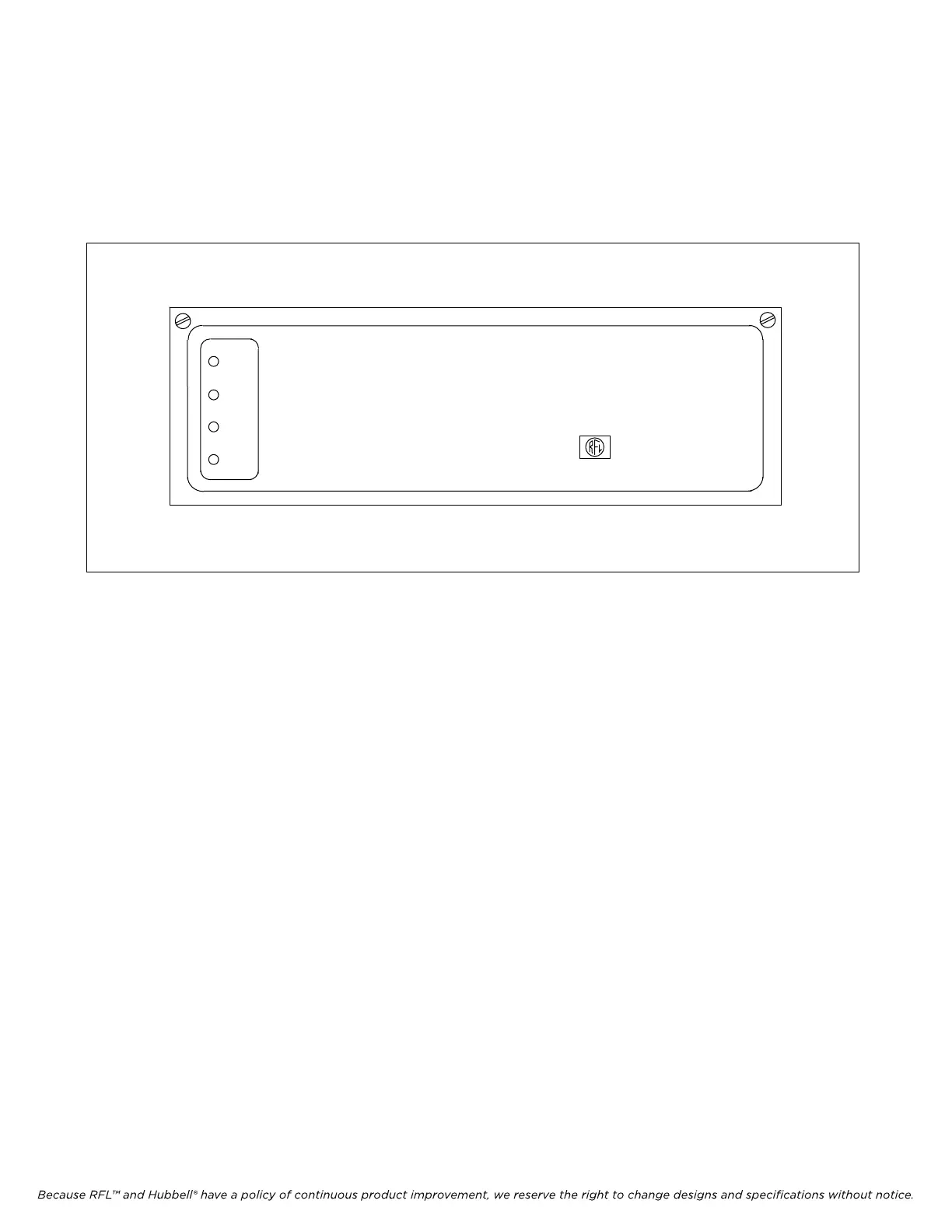
When the IMUX 2000 Main Shelf front door is closed, four LED indicators are visible. These LEDs
are labeled: POWER, NORMAL, ALERT, and ALARM, as shown in Figure 2-20, and indicate the
operational status of the multiplexer at a glance. Table 2-4 gives a description of these indicators and
also includes a description of the power supply fail indicator and the alarm cutoff switch.
POWER
NORMAL
ALERT
ALARM
Intelligent Multiplexer
IMUX 2000
RFL Electronics Inc.
Figure 2-20. Front view of main shelf with door closed, showing the system status indicators
IMUX 2000E1 RFL Electronics Inc.
April 1, 2007 2-31 (973) 334-3100