Because RFL™ and Hubbell® have a policy of continuous product improvement, we reserve the right to change designs and specifications without notice.
2.3.4.2 Optical Interface Adapters (OIAs)
Optical interface adapters are used to connect the IMUX 2000 to a E1 network using fiber optic cables.
There are five types of CM4 optical interface adapters available which can be used for redundant or
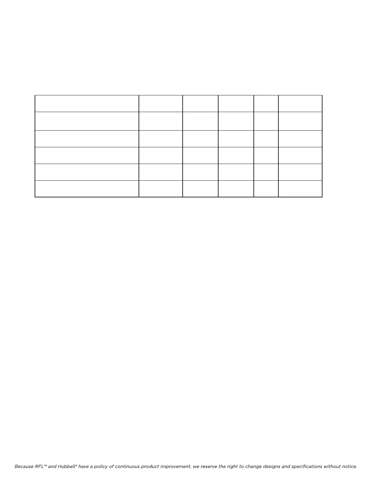
non-redundant applications. The characteristics of the five types of OIAs are shown in Table 2-2.
Ta
ble 2-2. Characteristics of IMUX 2000 CM4 Optical Interface Adapters
Model Designation Part Number Wavelength Fiber Type Light
Source
Application
1300-nm SM LED OIA-R CM4 107455-201 1300 nm Singlemode LED Redundant or
Non-redundant
1300-nm MM LED OIA-R CM4 107455-301 1300 nm Multimode LED Redundant or
Non-redundant
1300-nm SM LASER OIA-R CM4 107455-401 1300 nm Singlemode Laser Redundant or
Non-redundant
1550-nm SM LASER OIA-R CM4 107455-501 1550 nm Singlemode Laser Redundant or
Non-redundant
1550-nm SM 2mW LASER OIA-R CM4 107455-601 1550 nm Singlemode Laser Redundant or
Non-redundant
The CM4 OIAs consist of two sub-assemblies; a Light Interface Board (LIB), and a Redundant I/O
Board (MA-217A) which are mounted together to form one module as shown in Figure 2-15. Each
board has a thirty pin female connector which mates with a corresponding connector on the IMUX
2000 chassis which interfaces with the CM4 modules through the motherboard. In addition to this,
electrical connections between the two boards are made using interlocking headers.
The LIB has two fiber optic type ST connectors, one for the transmit fiber optic cable, and one for the
receive fiber optic cable. A DIP switch SW1 (See Figure 5-4) is provided for “Mode”selection
(Terminal, DI-A or DI-B), and five test points (TP1 - TP5) are provided for signal monitoring.
The MA-217A has three customer interface connections; an RS-232 connector (DB-9 male) for remote
configuration, a 6-position modular jack for external timing, and a BNC connector for E1 output.
IMUX 2000E1 RFL Electronics Inc.
April 1, 2007 2-24 (973) 334-3100