Because RFL™ and Hubbell® have a policy of continuous product improvement, we reserve the right to change designs and specifications without notice.
3.1.6 REDUNDANT MODE STATUS INDICATORS.
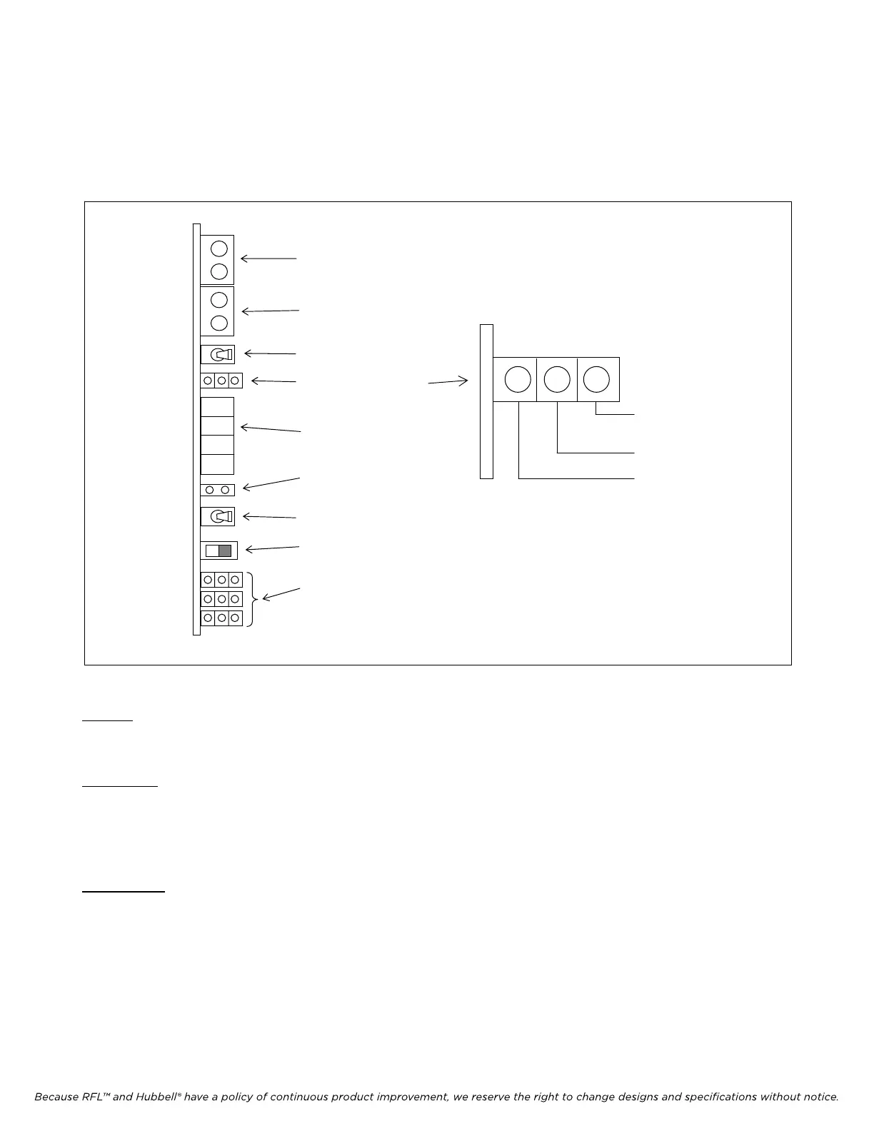
Front-panel LED indicators convey information on the current state of a Redundant-Mode system.
Three LED indicators represent the state of the module on which they are located, as shown in Figure
3-5.
Equip Mon Equip Mon Group CONFIG FUNCTION ON SET R-MAIN EXT ERR FRM
E1 Out E1 In BRD OK OFF NEXT C-AUTO INT LPBK BPV
ACTIVE L-SLAVE LOOP TX RX
M
DE
E1 OUTPUT
TEST JACKS
E1 INPUT
TEST JACKS
GROUP SWITCH
ACTIVITY INDICATORS
4-CHARACTER
FUNCTION DISPLAY
ON/OFF BI-LEVEL
DISPLAY
SET/NEXT SWITCH
3-POSITION
MODE SLIDE SWIT
CH
FRONT PANEL
LED INDICATORS
Configured
Board OK / Booting
Active
Figure 3-5. CM4 activity indicators
Active:
The LED Indicator is lit when the Common Module is active (driving the backplane signals).
Board OK:
The LED Indicator is lit when the Common Module determines that its on-board functions are
operating properly. The Indicator blinks during initial power-up boot delay, during which no
redundant-mode operation takes place.
Configured:
The LED Indicator is lit when the inactive Common Module receives its first complete
configuration set after power-up, or after becoming inactive due to a swap. An active module is
by definition configured and its indicator is always lit.
The Current state of a CM4 Common Module can also be determined over a network management link
(RS-232 or NCM[E1]).
IMUX 2000E1 RFL Electronics Inc.
January 23, 2004 3-8 (973) 334-3100