Because RFL™ and Hubbell® have a policy of continuous product improvement, we reserve the right to change designs and specifications without notice.
9.2.3 TYPICAL IMUX 2000 LOOPBACK PROCEDURE
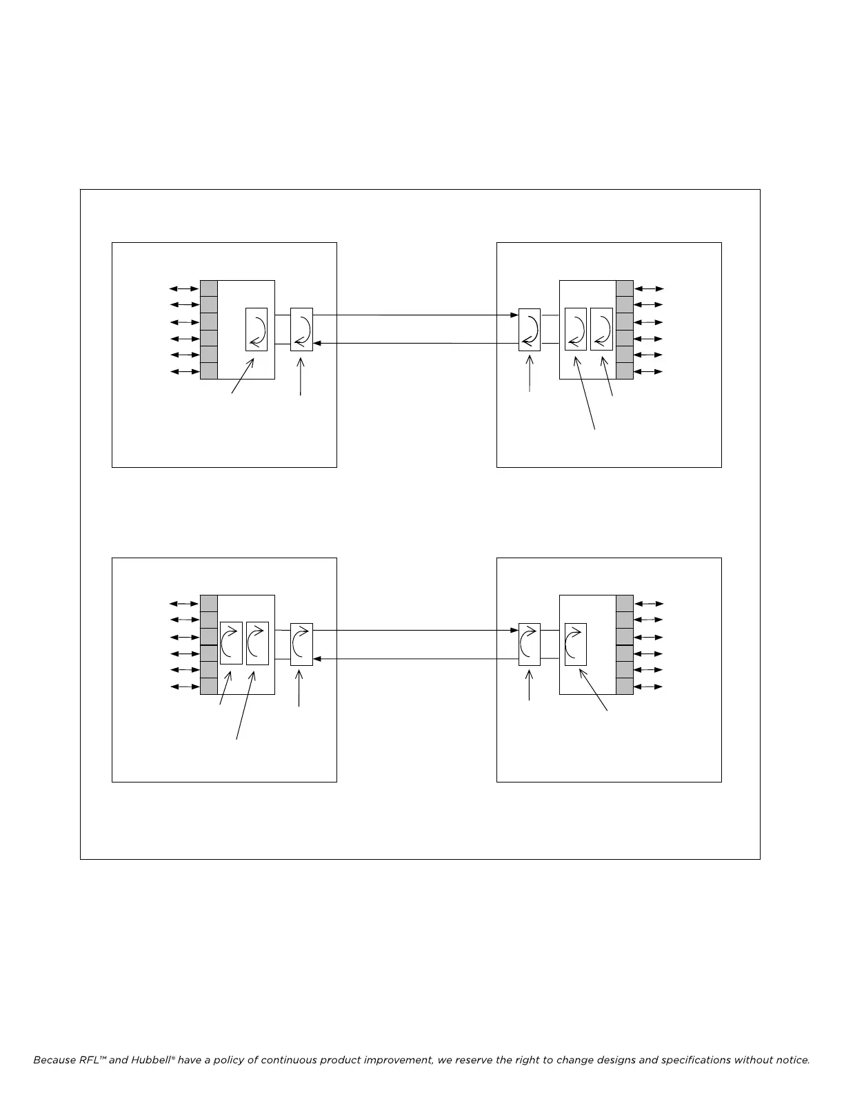
The following example shows how to use the loopbacks built into IMUX 2000 multiplexers to isolate a
failure on a point-to-point E1 system (Figure 9-2).
a. Testing from Location 1 to Location 2.
b. Testing from Location 2 to Location 1.
E1
CIRCUIT
LOCATION 1
IMUX 2000
VOICE
AND
DATA
CIRCUITS
LOCATION 2
IMUX 2000
VOICE
AND
DATA
CIRCUITS
DSX-1
or
EQUIP.
JACKS
EQUIPMENT
LOOPBACK
MANUAL
LOOPBACK
(PATCHCORD
OR JUMPER
CONNECTOR)
DSX-1
PAYLOAD
LOOPBACK
LINE
LOOPBACK
MANUAL
LOOPBACK
(PATCHCORD)
E1
CIRCUIT
LOCATION 1
IMUX 2000
VOICE
AND
DATA
CIRCUITS
LOCATION 2
IMUX 2000
VOICE
AND
DATA
CIRCUITS
DSX-1
or
EQUIP.
JACKS
EQUIPMENT
LOOPBACK
MANUAL
LOOPBACK
(PATCHCORD
OR JUMPER
CONNECTOR)
PAYLOAD
LOOPBACK
LINE
LOOPBACK
MANUAL
LOO
PBACK
(PATCHCORD)
DSX-1
Figure 9-2. Using IMUX 2000 E1 loopbacks
IMUX 2000E1 RFL Electronics Inc.
January 23, 2004 9-3 (973) 334-3100