Because RFL™ and Hubbell® have a policy of continuous product improvement, we reserve the right to change designs and specifications without notice.
10.3 ALARM I/O MODULE
10.3.1 DESCRIPTION
The Power Supply Alarm I/O module consists of an EMI filter, an SWC filter, relay logic, an alert
relay and a fail relay. These components can be seen in Figure 2-11 which also includes the power
supply module and the system status indicators that are associated with the IMUX 2000. These
indicators and relays respond to fault conditions on Common Modules, channel modules, or the power
supply module itself.
When a Main Shelf is equipped with a main power supply and a redundant power supply it will have
only one Power Supply Alarm I/O module. The relays on the Power Supply Alarm I/O module will
respond to alarm and alert conditions from both power supply modules. This insures that Fail and/or
Alert monitoring continues even if one or the other supply is removed. Note that because the
corresponding relay contacts on the Main and Redundant supplies are connected in parallel, the ACO
switches on both must be switched “on” to activate the alarm cut-off, and both must be switched “off”
to de-activate the alarm cut-off.
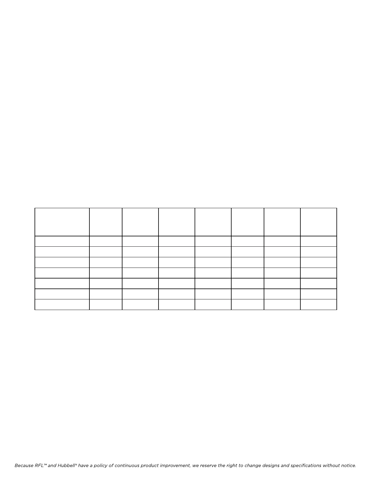
Each Alarm I/O module operates with a specific Power Supply module. Refer to the table below for
application information.
Table 10-3. Power Supply Alarm I/O Application Information
Power Supply→
Alarm I/O
↓
9547-840 9547-910 9547-920 9547-930 9547-950 9547-960 9547-970
9547-18801 X
9547-18802
9547-18804 X X
9547-18805 X
9547-18806 X X
9547-18807 X X
9547-18808 X
10.3.2 THEORY OF OPERATION
U51, U52, K51, K52, and their associated components form the alarm I/O circuitry for the IMUX 2000
multiplexer. Operation of relays K51 and K52, as well as annunciation indicators DS1 through DS5 are
described in Section 2 of this manual.
Logic signals controlling the alarm circuitry are interfaced with the chassis motherboard through edge
connector terminals (See P2 in Figures 10-10, 10-12 and 10-14). After processing, normal and alarm
conditions are annunciated by LED indicators DS1 through DS5 and relays K51 and K52. The
indicators are mounted along the front edge of the power supply board, and can be viewed with the
shelf door closed.
The relay contacts are wired to TB2 as shown in Figure 10-10, 10-12 and 10-14. One Form C contact
per relay is provided, rated 100 mA @ 300 Vdc (resistive).
IMUX 2000E1 RFL Electronics Inc.
January 1, 2008 10-9 (973) 334-3100