Because RFL™ and Hubbell® have a policy of continuous product improvement, we reserve the right to change designs and specifications without notice.
2.3.3.4 Multiplexing Of Channels To Form E1 Aggregate
The multiplexer develops backplane bus synchronization signals. The transmit section of each channel
module synchronizes to these signals, and places its data onto the selected bus. The multiplexer then
forms the aggregate signal, using the selected framing format.
2.3.3.5 Multiplexer/Demultiplexer Bus Interface To Channels
The CM4 uses tri-state bus drivers and receivers to permit routing the demultiplexer and multiplexer
bus signals to either of two backplane buses (Bus A or Bus B). This versatile bus capability enables
simple configuration of a multiplexer as either "terminal" or "drop/insert."
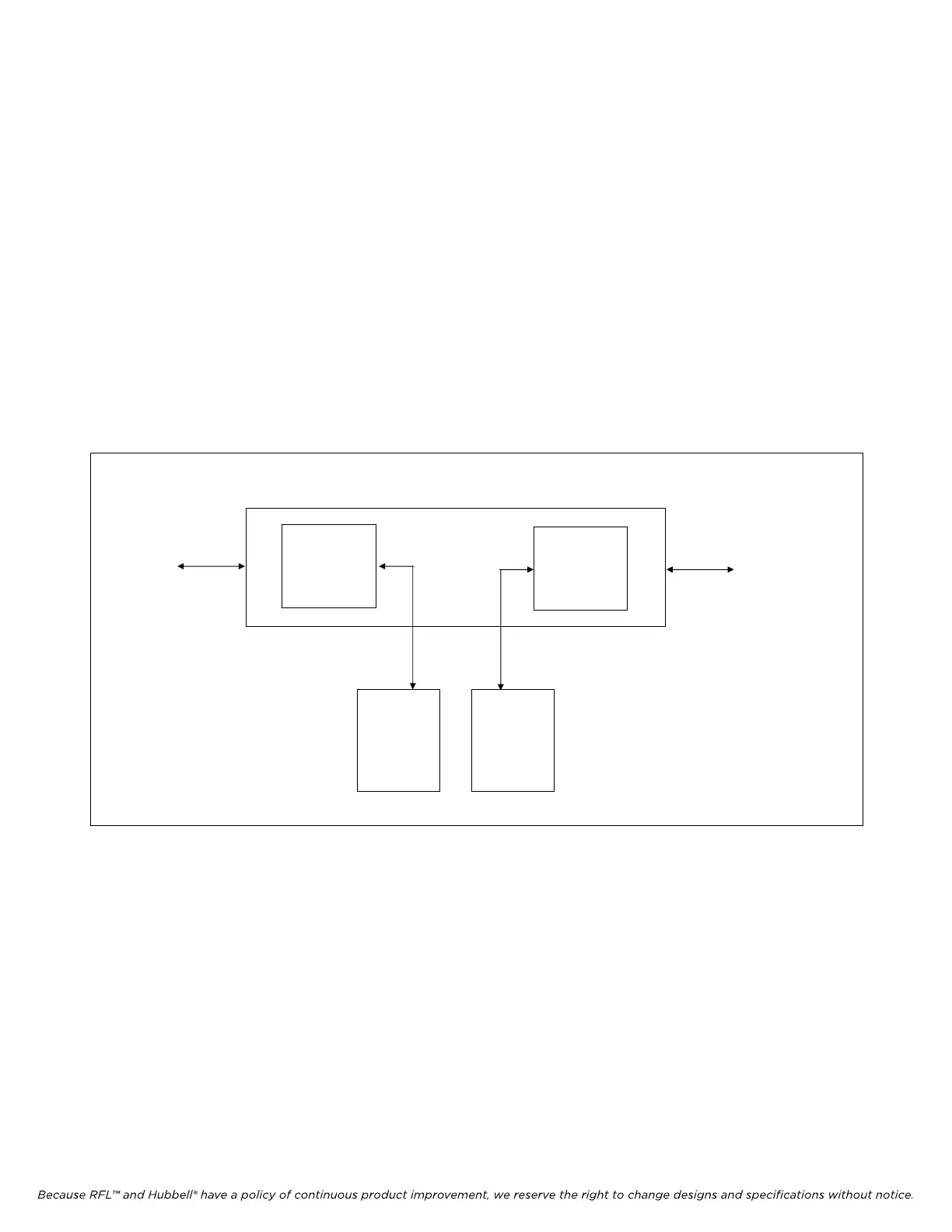
Bus A/B nomenclature is used to set channel modules to transmit and receive through a desired drop-
and-insert port. In order to transmit out of drop-and-insert A, or out of a terminal shelf, a channel
module is set to operate on Bus A. In order to transmit out of drop-and-insert B, a channel module is
set to operate on Bus B. This can be seen in Figure 2-9.
TERMINAL
OR
DI/A
DI/B
CHANNEL
MODULE
SET TO
BUS B
CHANNEL
MODULE
SET TO
BUS A
Figure 2-9. The meaning of Bus A and Bus B channel module settings
2.3.3.6 Transmit Timing Functions
The CM4 enables the selection of LOOP, INTERNAL, EXTERNAL, or THRU timing. In addition to
primary timing, the CM4 provides a fallback timing setting. Fallback timing takes effect automatically
when conditions cause a loss of primary timing; for example, in case of frame loss when LOOP is the
primary timing setting. Refer to Application Notes (Section 20) for suggested settings of fallback
timing.
IMUX 2000E1 RFL Electronics Inc.
April 1, 2007 2-13 (973) 334-3100