Because RFL™ and Hubbell® have a policy of continuous product improvement, we reserve the right to change designs and specifications without notice.
Section 2. FUNCTIONAL DESCRIPTION OF THE IMUX 2000 INTELLIGENT
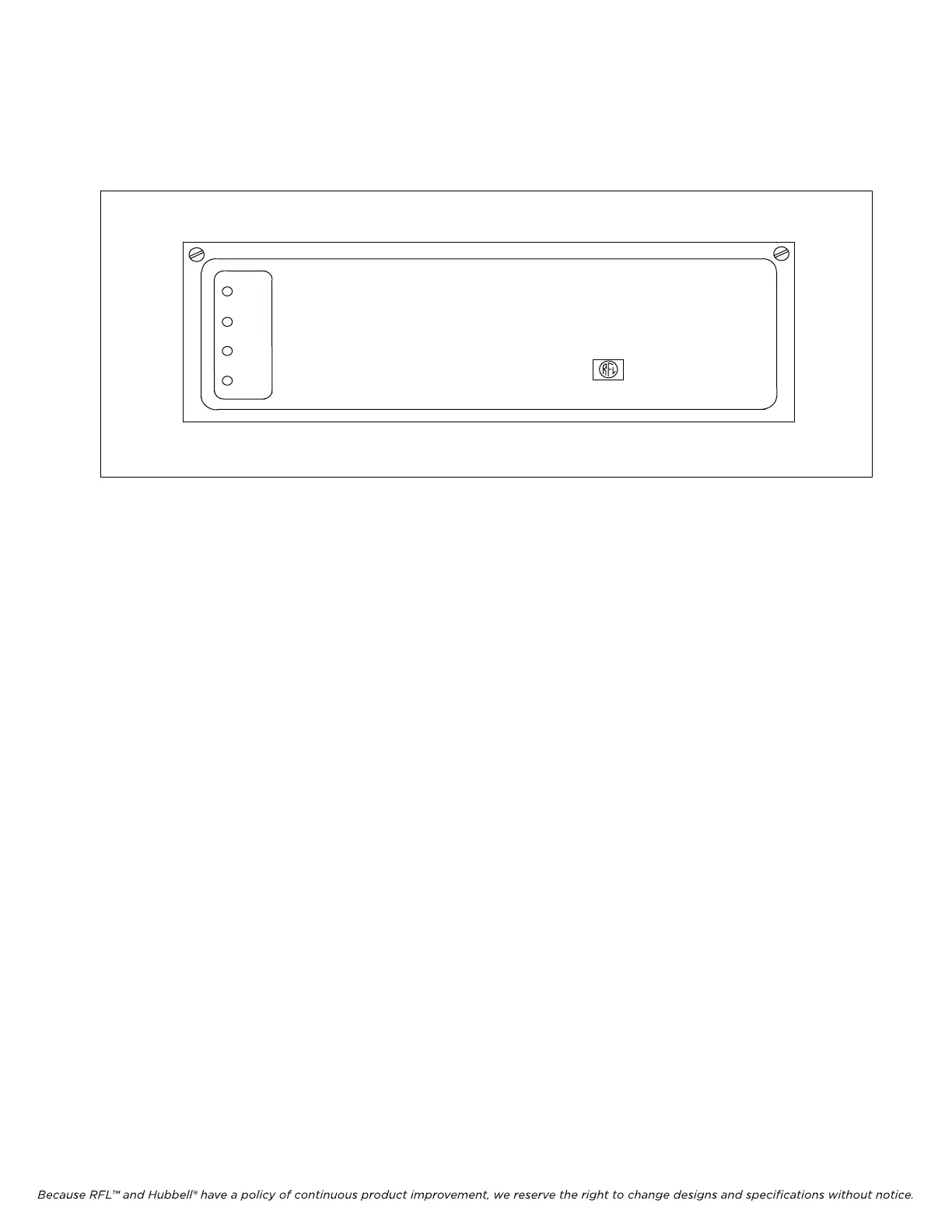
E1 MULTIPLEXER
POWER
NORMAL
LERT
LARM
IMUX 2000
Intelligent Multiplexer
RFL Electronics Inc.
Figure 2-1. Front panel of IMUX 2000 Interlligent E1 Multiplexer
2.1 INTRODUCTION
This section gives a functional description of the IMUX 2000 Intelligent E1 Multiplexer, including
how the unit can be configured for both point-to-point and drop/insert electrical and fiber E1 systems.
This section also defines all common equipment connectors, switches, and indicators used in the
IMUX 2000 Intelligent E1 Multiplexer.
2.2 MULTIPLEXER CONFIGURATIONS AND SYSTEMS
The IMUX 2000 Intelligent E1 multiplexer can be configured as a terminal multiplexer or as a
drop/insert multiplexer. Both of these configurations can be fitted with an electrical E1 interface or an
optical E1 interface using a variety of interface adapters. The optical interface adapters permit the E1
circuit to operate over a fiber optic cable and are available in both multimode and single-mode
configurations at several different wavelengths.
IMUX 2000E1 RFL Electronics Inc.
April 1, 2007 2-1 (973) 334-3100