Because RFL™ and Hubbell® have a policy of continuous product improvement, we reserve the right to change designs and specifications without notice.
2.5 MULTIPLEXER, REAR PANEL CONNECTIONS
Figure 2-22 shows the power and signal connectors located on the rear panel of the Main Shelf of a
Multiplexer Terminal using an MA-270R Module Adapter. Figure 2-23 is similar to Figure 2-22, but it
shows the Optical Interface Adapter (OIA) used when interfacing to fiber optic cables.
All E1 signal and timing connections to a CM4 are made through its corresponding MA-275R Module
Adapter or Optical Interface Adapter (OIA). A terminal multiplexer contains one MA-275R or OIA,
while a drop/insert multiplexer contains two.
Table 2-14 lists the terminal assignments for the input power terminal strip on the rear of the Main
Shelf. Table 2-15 lists the terminal assignments for the ALARMS terminal strip that is directly below
the input power terminal strip. Table 2-16 provides the pin assignments for the E1 I/O connector on the
MA-270R. Table 2-17 lists the pin assignments for the REMOTE connector on the MA-270R; these
assignments are that same as for the RS-232 connector on the OIA.
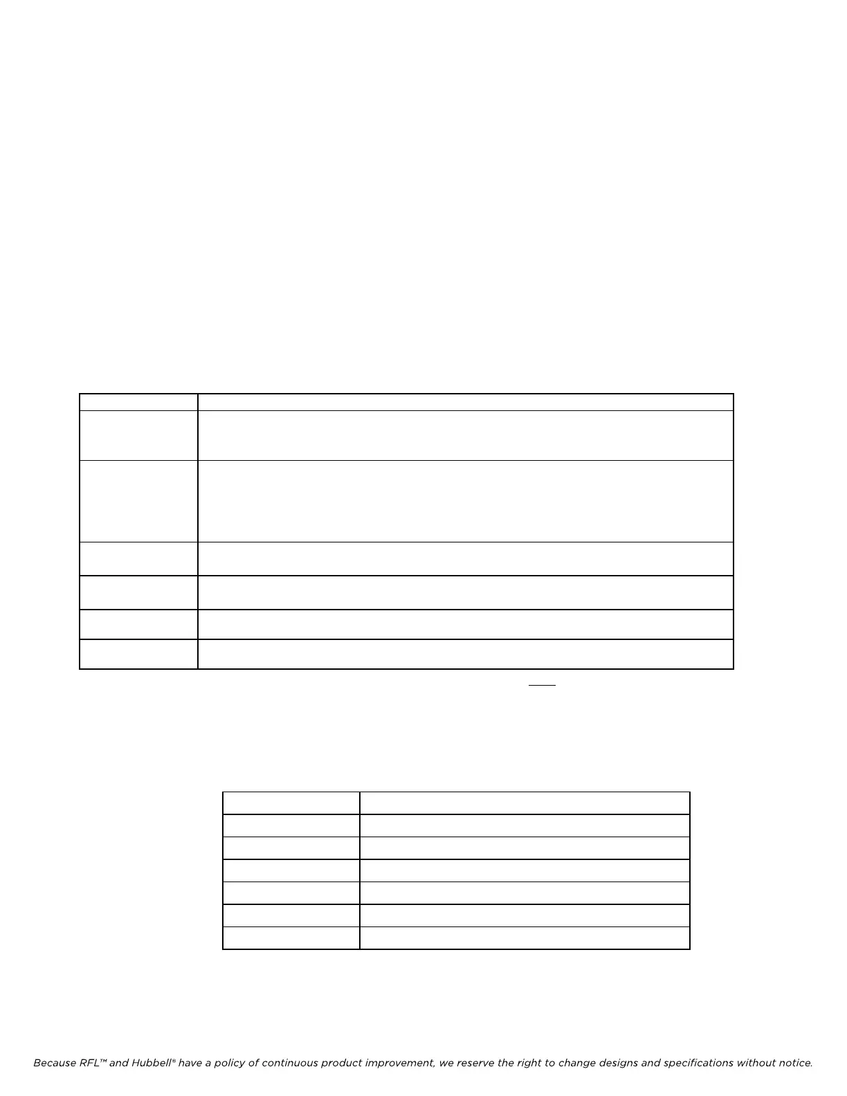
Table 2-14. Terminal assignments, main shelf input power terminal strip
Terminal Label Description (Refer to Figures 8-2 and 8-3)
RG (RING GEN) For connection to an external ring generator referenced to SIG BAT. Connect one side of the
ring generator to the RING GEN terminal, and the other side to the SIG BAT terminal.
(1)
SB (SIG BAT) For connection to an external signaling voltage source when signaling voltage is required by
one or more channel modules. SIG BAT is normally jumpered to NEGATIVE BAT when
the dc power voltage is the same as the desired signaling voltage. The SIG BAT input may
also be connected to an external loop current generator.
(1)
+R (+BAT R)
Redundant station battery positive.
(2)
-R (-BAT R)
Redundant station battery negative.
(2)
+ (+BAT) Station battery positive. Voltage must match input requirements of power supply module.
- (-BAT) Station battery negative. Voltage must match input requirements of power supply module.
1. To prevent damage to the equipment, the source connected to this input must be externally fused or current-
limited.
2. Redundant station battery connections are only used when the shelf is equipped with a redundant power supply.
The voltage must match the input requirements of the redundant power supply module.
Table 2-15. Terminal assignments, main shelf rear-panel ALARMS terminal strip
Terminal Label Description
ALERT relay N.O. contact (normally-open).
ALERT NO
ALERT COM ALERT relay COM contact (common).
ALERT NC ALERT relay N.C. contact (normally-closed).
ALARM NO ALARM relay N.O. contact (normally-open).
ALARM COM ALARM relay COM contact (common).
ALARM NC ALARM relay N.C. contact (normally-closed).
IMUX 2000E1 RFL Electronics Inc.
April 1, 2007 2-42 (973) 334-3100