Because RFL™ and Hubbell® have a policy of continuous product improvement, we reserve the right to change designs and specifications without notice.
IMUX 2000E1 RFL Electronics Inc.
April 1, 2007 2-2 (973) 334-3100
2.2.1 TERMINAL MULTIPLEXER
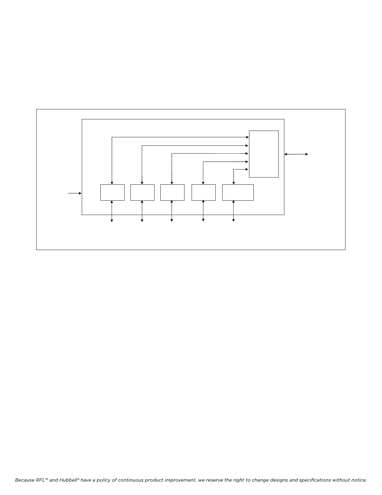
The terminal multiplexer serves as an interface between a single E1 "high-speed" circuit and multiple
voice and data "low-speed" circuits (See Figure 2-2). Channel modules convert voice and data signals
into a single or multiple 64,000-bit/second (64-kbps) digital signals. These 64-kbps signals or "time
slots" are then combined by time division multiplexing (TDM) into an E1 signal. The multiplexed
voice and data circuit becomes payloads within the E1 circuit.
CHANNEL
MODULES
E1 CIRCUIT
(ELECTRICAL OR
FIBER)
VOICE
MODULE
VOICE
MODULE
DATA
DATA
MODULE
ORDERWIRE
MODULE
COMMON
MODULE(S)
P A Y L O A D C I R C U I T S
TERMINAL MULTIPLEXER
Figure 2-2. Terminal multiplexer (sample configuration)
A single E1 circuit provides 32 full-duplex, 64-kbps time slots for an aggregate payload capacity of
2.048 Mbps in each direction. The time slots are numbered 0 through 31. Time slot 0 is reserved for
system use, and if CAS (Channel Associated Signaling) is used, time slot 16 is dedicated to this
function. Time slot 30 is used for fast reframe function, if enabled. See Section 12 for more
information on E1 framing.