Because RFL™ and Hubbell® have a policy of continuous product improvement, we reserve the right to change designs and specifications without notice.
5.20 USING THE ALARM CUT-OFF SWITCH
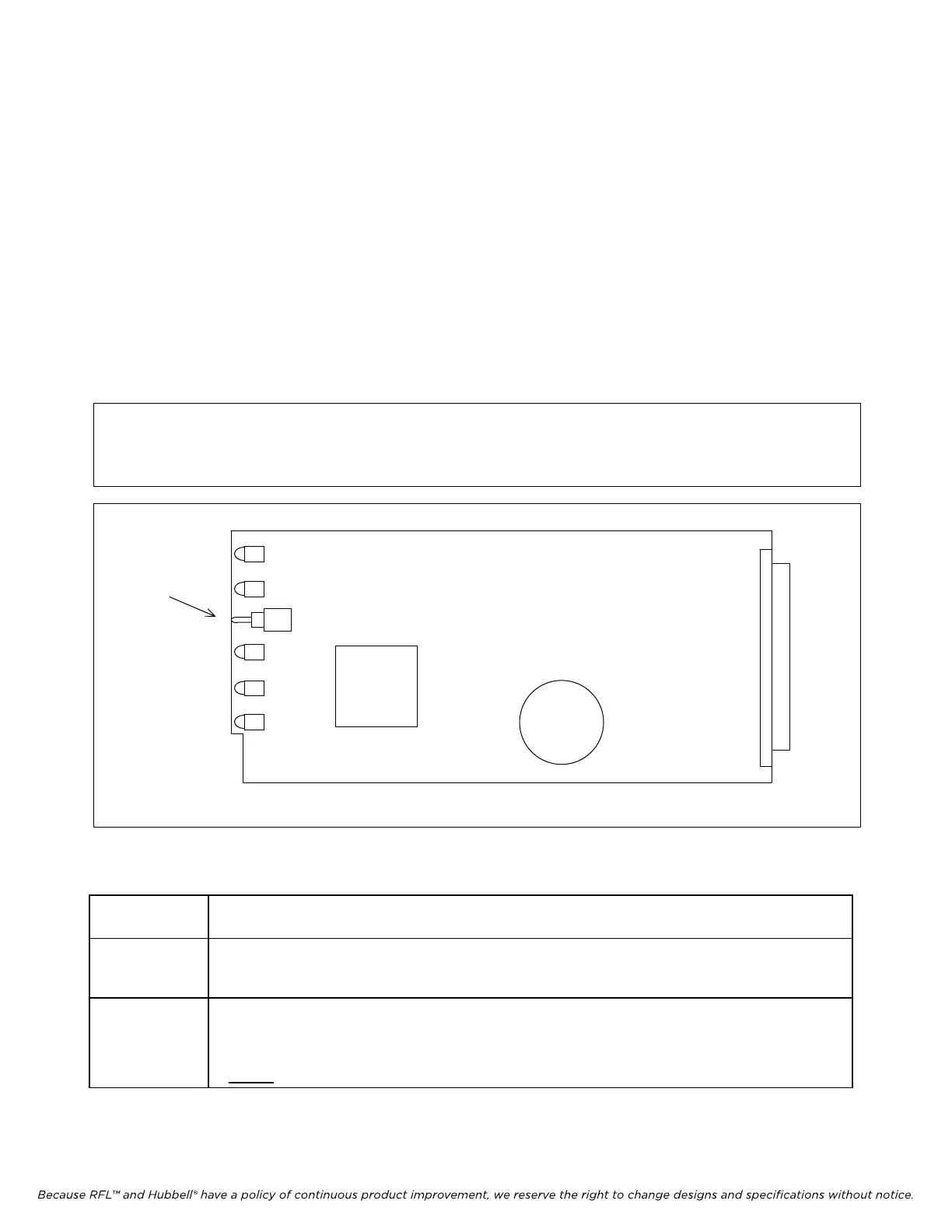
The IMUX 2000 Alarm Cut-Off (ACO) switch is located on the power supply module (Figure 5-16).
When the ACO switch is in the EN position, the main shelf ALARM and ALERT relays located on the
Power Supply Alarm I/O module will respond to detected alarm and alert conditions. However, when
the ACO switch is in the DIS position, these relays are disabled. That is, they are forced into their
normal (non-alarm) state. (See Table 5-11.)
The ACO switch on an IMUX 2000 multiplexer may be used to silence a local alarm once this
multiplexer has been identified as the source of the alarm. After the alarm or alert producing condition
has been fixed, be sure to return the ACO switch to its EN position to re-enable the ALARM and
ALERT relays.
NOTE
In multiplexers equipped with two power supplies, both ACO switches must be placed
in the DIS position to disable the ALARM and ALERT relays located on the Power
Supply Alarm I/O module
IMUX 2000E1 RFL Electronics Inc.
ACO
SWITCH
Figure 5-16. Location of the alarm cut-off (ACO) switch on the Power Supply module
Table 5-13. Using the ACO switch
Switch
Position
Description
The ALARM and ALERT relays located on the Power Supply Alarm I/O module are enabled. If an
EN
alarm or alert condition is detected, they will change
position accordingly.
Whe
n the condition
ceases, the relays will return to normal.
DIS The ALARM and ALERT relays located on the Power Supply Alarm I/O module are disabled. They
will stay in their normal positions, even if an alert or alarm condition occurs.
If the shelf is equipped with a second (redundant) power supply, the ACO switches on
BOTH
power supplies must be in the DIS position to disable the ALARM and ALERT relays.
January 1, 2008 5-40 (973) 334-3100