Because RFL™ and Hubbell® have a policy of continuous product improvement, we reserve the right to change designs and specifications without notice.
6.3.1 NETWORK COMMUNICATION PATHS
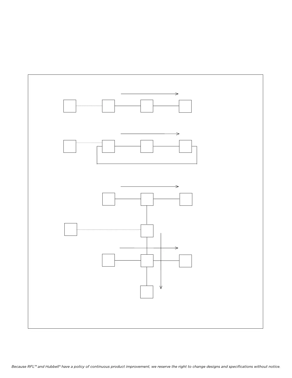
Each node in a network is connected to another node, allowing communication to pass from one node
to another. Each communication path must have a beginning and an end as shown in the Figures
below. Each box represents a node in the network. When using the Network Management Software,
the PC can be connected to any node in the network.
PC
PC
PC
1
2
3
1
2
3
1 2
3
4
5
6
7
8
Simple Network With
One Communication
Path and Three Nodes
Simple Network With One
Loop, One Co
mmunication
Path and Three Nodes
Network With Three
Communication
Paths and Eight Nodes
Beginning
End
Beginning
End
Beginning
End
Beginning
End
Beginning
End
Note: The numbers in each box represent node numbers
Figure 6-7. Typical networks and comm
unications paths
IMUX 2000E1 RFL Electronics Inc.
February 28, 2006 6-9 (973) 334-3100