Because RFL™ and Hubbell® have a policy of continuous product improvement, we reserve the right to change designs and specifications without notice.
8.3 SYSTEM CHECK-OUT PROCEDURES
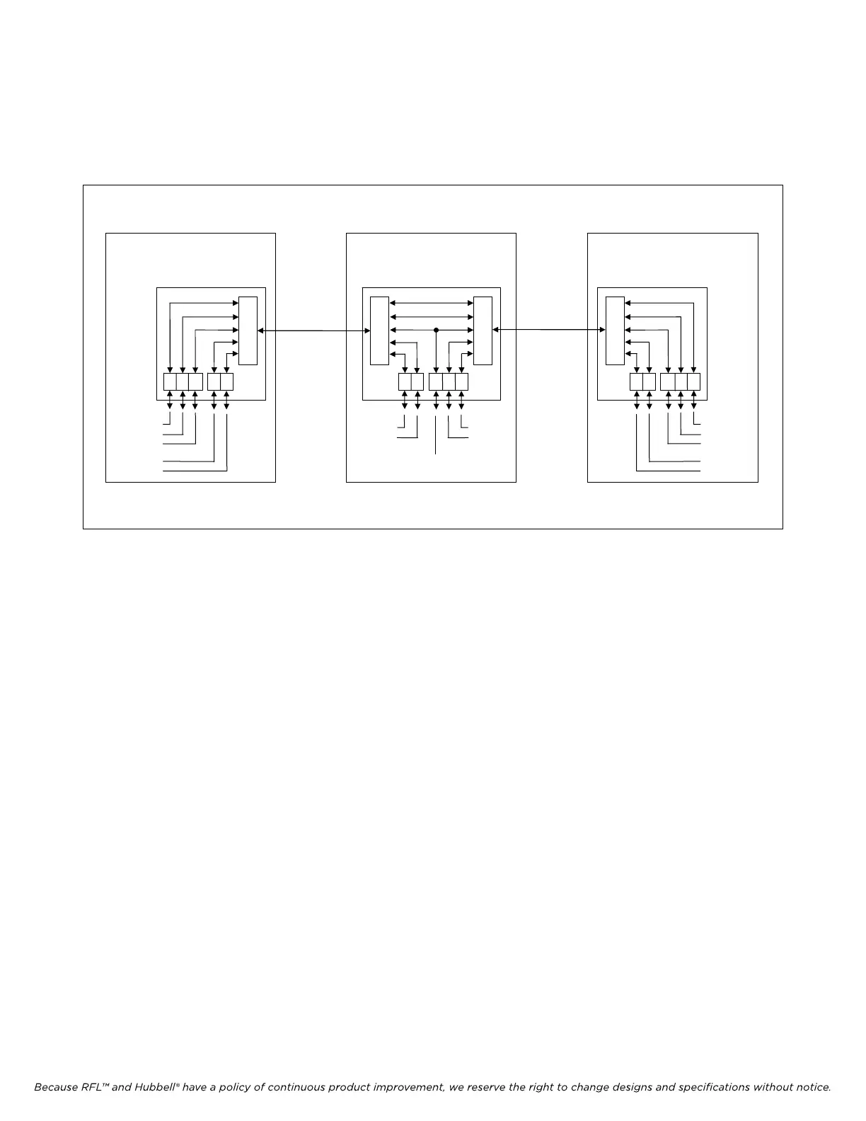
The system check-out procedures in this section are general guides. They illustrate how to check out a
typical three-location IMUX 2000 drop/insert system. (See Figure 8-6.)
V D
OW
V
D
E1
ORDER WIRE
VOICE 1
DATA 1
VOICE 2
DATA 2
LOCATION 1
IMUX 2000 TERMINAL
MULTIPLEXER
VD OW
V
D
E1
ORDER WIRE
VOICE 1
DATA 1
VOICE 3
DATA 3
LOCATION 3
IMUX 2000 TERMINAL
MULTIPLEXER
D V
V
D
E1
E1
E1
CIRCUIT
E1
CIRCUIT
LOCATION 2
IMUX 2000
DROP/INSERT
MULTIPLEXER
OW
DATA 3
V
I
E
DATA 2
VOICE 2
ORDER WIRE
Figure 8-6. Typical three-terminal IMUX 2000 system
When checking out an IMUX 2000 system, follow these overall guidelines:
1. Start at the terminal multiplexer that is internally or externally timed.
If both terminal multiplexers are loop-timed, start at either end.
2. Perform the check-out procedures at locations in the order in which they appear in the system.
3. Test each location locally before performing system tests.
4. After performing the system-level tests described in this section, you may also wish to test the
individual circuits formed by the channel modules in the multiplexers. Consult the individual
channel module Instruction Data Sheets in Sections 14 through 19 of this manual for
recommended test procedures for each type of circuit.
The following procedures do not specify the use of E1 test equipment. However, you may need E1 test
sets in some instances, such as to isolate an intermittent trouble in either a E1 facility or a multiplexer.
IMUX 2000E1 RFL Electronics Inc.
January 23, 2004 8-12 (973) 334-3100