Because RFL™ and Hubbell® have a policy of continuous product improvement, we reserve the right to change designs and specifications without notice.
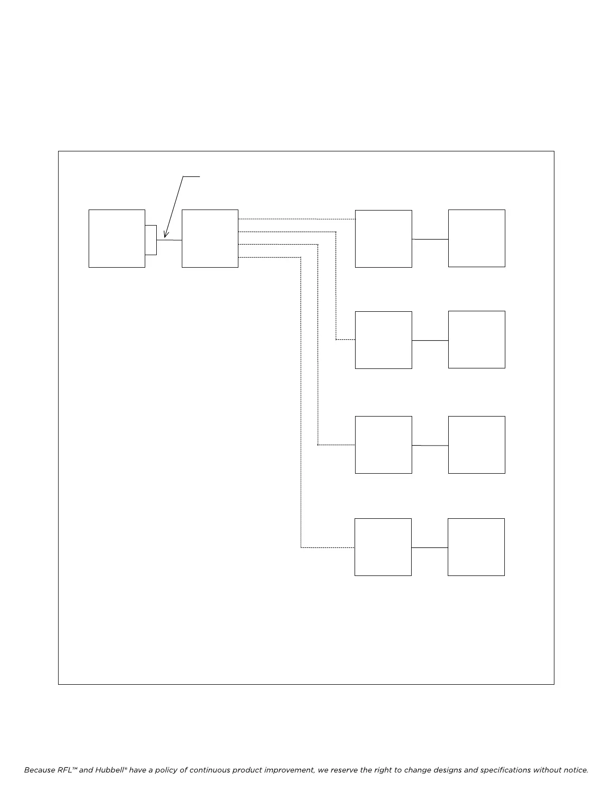
Figure 6-5 shows a PC at a remote location connected to 4 nodes, where each node is in a different
network. Phone line #1 through phone line #4 each represent a different communication path.
Figure 6-6 shows a PC at a remote location connected to 4 nodes, where all nodes are in the same
network. The nodes communicate Network Management configuration information via the Facility
Data Link.
*
Null modem cable may be required.
PC
MODEM
MODEM
NODE 1
MODEM
NODE 2
MODEM
NODE 3
MODEM
NODE 4
PHONE LINE #1
PHONE LINE #2
PHONE LINE #3
PHONE LINE #4
RS232 cable
*
*
*
*
Figure 6-5. PC at a remote location connected to 4 nodes, where each node is a different network
IMUX 2000E1 RFL Electronics Inc.
February 28, 2006 6-7 (973) 334-3100