Because RFL™ and Hubbell® have a policy of continuous product improvement, we reserve the right to change designs and specifications without notice.
6.5.3.7.1.1 DACS-R DS0 Map 0
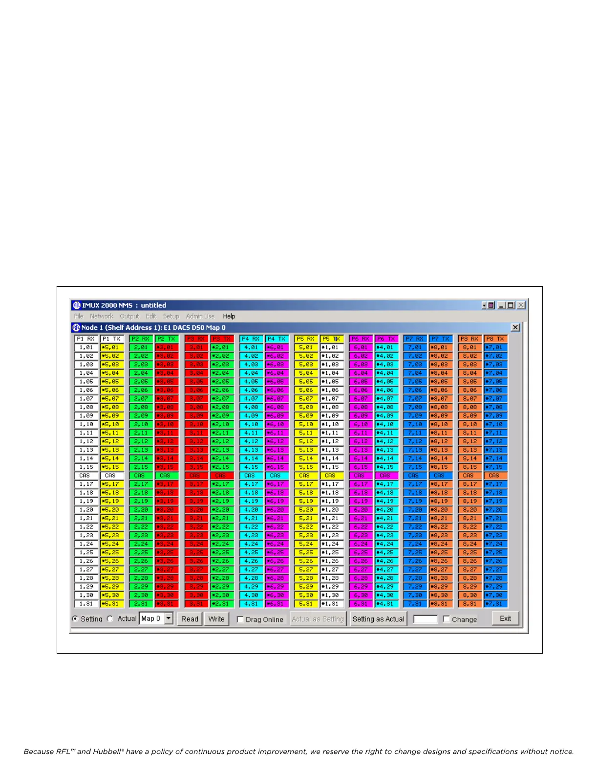
The DACS-R maps can be programmed using windows similar to the one shown in Figure 6-18.
The DACS DS0 map is what defines how E1 data is transferred from the receive ports to the transmit ports. The DS0 map
is only applicable to ports that have a path type of XC (cross connect), the following discussion assumes that the paths are
set for XC type.
The user may send any incoming DS0 out on any one or more outgoing DS0(s). In order to accommodate this, the user
configures the Tx DS0 by defining what incoming data is to be used (to transmit). By configuring where the Tx data comes
from rather than where received data is to be sent, multiple transmit DS0s may share a single Rx DS0.
After DS0 Map 0 is programmed, continue the programming procedure for DS0 Maps 1 through 7 in a similar fashion
according to your system requirements. After all eight DS0 maps have been programmed click on the “Exit” box at the
bottom of the window to return to the previous window (the Redundant DACS Configuration And Status window) as
shown in figure 6-17.
When finished with either viewing or changing the other DACS settings, click on Exit. This will return you to the
Display/Change Node window where you can select the next card. Go back to the Display/Change Node window and click
on the CM “TERM” button. This will bring you to the CM4 Configuration And Status window as shown in Figure 6-19.
Figure 6-18. DACS-R DS0 Map 0
IMUX 2000E1 RFL Electro
nics Inc.
February 28, 2006 6-26 (973) 334-3100
 Loading...
