Because RFL™ and Hubbell® have a policy of continuous product improvement, we reserve the right to change designs and specifications without notice.
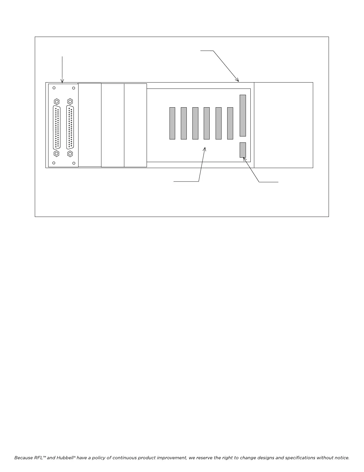
JP40
SLOT
1
SLOT
2
SLOT
3
SLOT
4
SLOT
5
SLOT
6
REMOVE MODULE ADAPTORS IN THE FIRST FIVE OR
SIX SLOTS TO INSTALL REPEATER CABLE IF
ACCESS IS NOT AVAILABLE FROM ABOVE OR BELOW
THE SHELF
REPEATER
POWER
CONNECTOR
OPENING IN TOP AND
BOTTO
M OF SHELF FOR
REPEATER POWER CONNECTOR
MA-500
BUS IN BUS OUT
BUS REPEATER
MODULE ADAPTER
Figure 8-1. Rear view of Main or Repeater Shelf showing Bus Repeater Module and Repeater signal and power
connectors.
5. If the Repeater Shelf will be powered by the Main Shelf supply, connect the Repeater Power
cable between the Repeater Power connector on the Main Shelf and the Repeater Power
connector on the Repeater Shelf.
These connectors are labeled "JP 40", and are located at the lower right rear of
the shelves as shown in Figure 8-1. If the Repeater Shelf has its own power
supplies, the Repeater Power cable is not needed.
It may be necessary to remove several Module Adapters on both shelves to gain
access to the Repeater Signal and Power connectors. Be sure to re-install the
adapters after inserting the Repeater cables.
IMUX 2000E1 RFL Electronics Inc.
January 23, 2004 8-4 (973) 334-3100