Because RFL™ and Hubbell® have a policy of continuous product improvement, we reserve the right to change designs and specifications without notice.
RFL DA-191A RFL Electronics Inc.
July 23, 2001 5 (973)
334-3100
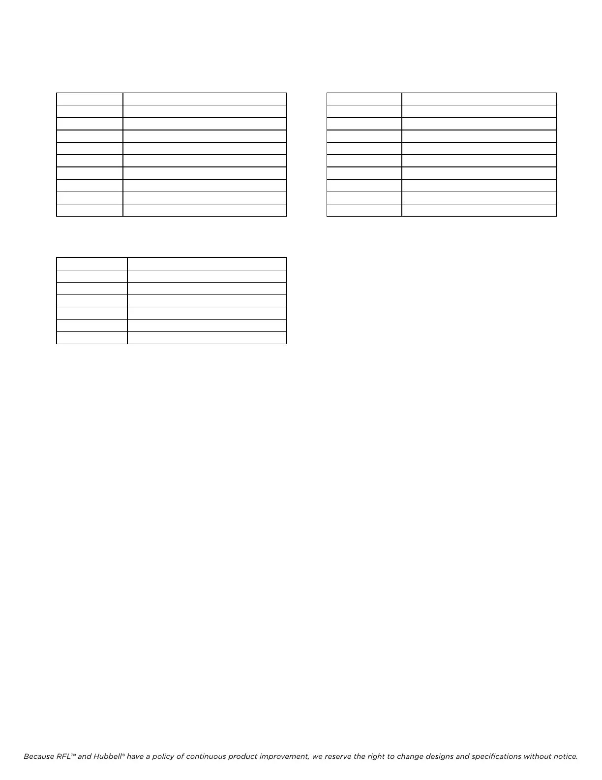
Table 1A. Wiring Assignments for MA-420A and MA-440A Table 1B. Wiring Assignments for MA-425
Module Adapters Module Adapter
Pin No. Si
gnal Name Pin No. Signal Name
1 Receive Line Signal Detect 1 TXA
2 Receive Data 2 TXB
3 Transmit Data 3 RXA
4 Not used 4 RXB
5 Signal Ground 5 Signal Ground
6 Not used 6 Not used
7 Not used 7 Not used
8 Clear To Send 8 Not used
9 Not used 9 Not used
Table 1C. Wiring Assignments for MA-404A
Module Adapter
RJ-11 Pin No. Signal Name RJ-11 Pin No. Signal Name
1 CTS (always on) 1 Send Data A
2 Transmit Data 2 Send Data B
3 Not used 3 Ground
4 Receive Data 4 Ground
5 Ground 5 Receive Data A
6 Carrier Detect 6 Receive Data B
4. Insert the Adapter Module into the rear of the shelf directly behind the module slot
where the DA-191A will be installed. Secure the module with the screws provided.
5. Connect the Adapter Module to the user equipment using the connector pin assignments
detailed in Table 1A or 1B as applicable, or connect the fiber to the appropriate remote unit as
listed below.
RFL MA-720, 722 & 726 - Dymec Model 5843 or 5844
RFL MA-724 - Dymec Model 5843S or 5844S
6. Refer to Figure 2 and Table 2 for the location of switches on the DA-191A.
7. On the DA-191A check the setting of DIP switch SW1-1 through SW1-3.
SW1-1 through SW1-3 (RATE 1, RATE 0, and MODE) controls the data port
configuration of the DA-191A. Set the switches to achieve the desired
configuration in accordance with Table 3.
8. On the DA-191A check the setting of DIP switch SW1-4 through SW1-8.
SW1-4 through SW1-8 (TIME SLOT SELECT) controls the transmit and receive
time slot of the DA-191A. Set the switches to achieve the desired time slot setting in
accordance with Table 4.