Because RFL™ and Hubbell® have a policy of continuous product improvement, we reserve the right to change designs and specifications without notice.
IMUX 2000E1 RFL Electronics Inc.
Jitter
Buffer
Select
Multiplexer
Demultiplexer
Frame
Synchronization
Timing
Select
Micro-
processor
Non-
Volatile
Memory
Front Panel User Interface
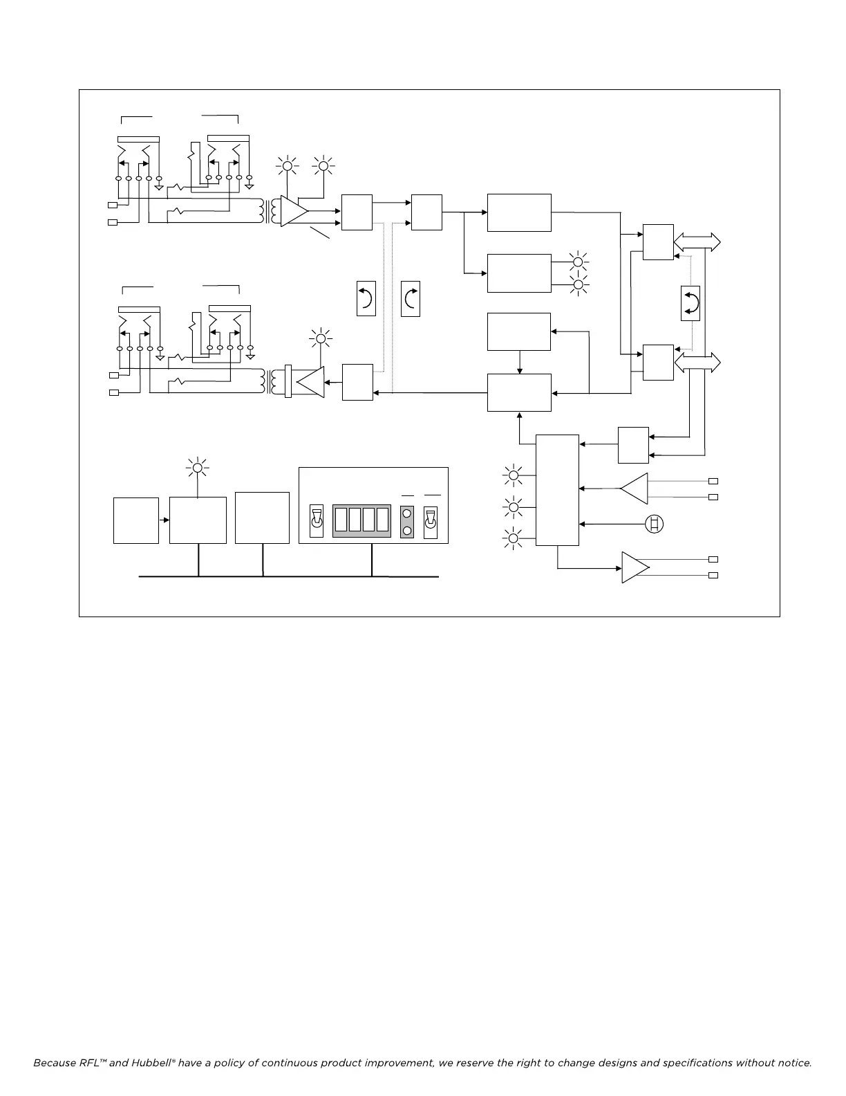
Figure 2-8. Functional diagram, CM4 Common Module, Communications Control
CM4 Status and Control Bus
Select
LOOP
EXT
INT
Loop or
Through
External
Internal
oscillator
Bus
Switch
A
Bus
Switch
B
Bus B
Bus A
FRM
ERR
Frame
Overhead
To/From
Channel
Modules
External
Timing
Input
Timing
Output
(RS-422)
RX IN BPV
Line Recovered
Receiver Timing
Data
Select
“DeMUX”
Bus
Equipment
Loopback
Line
Loopback
LBO
TX OUT
Line
Driver
LPBK
GROUP FUNCTION
ON
OFF
SET
NEXT
RS-232
Serial
Port
Payload
Loopback
110
430
430
EQUIP
MON
E1 IN
E1 Input
110
430
430
EQUIP
MON
E1 IN
E1 Output
April 1, 2007 2-11 (973) 334-3100