Because RFL™ and Hubbell® have a policy of continuous product improvement, we reserve the right to change designs and specifications without notice.
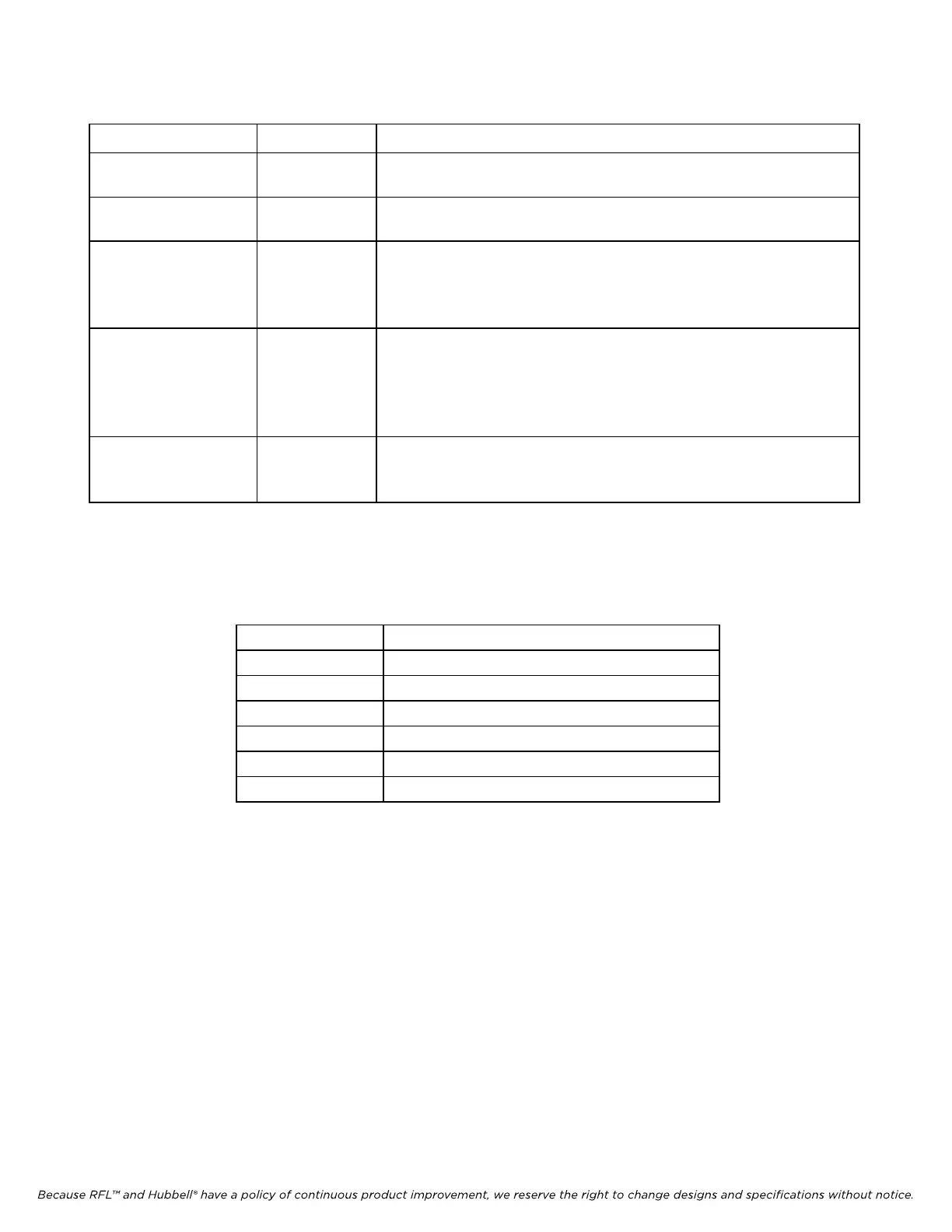
Table 2-16. Pin assignments, E1 I/O connector on the MA-270R/MA-275R Module Adapter
Pin Numbers Designation Description
1 (tip) and 9 (ring) T, R E1 Out; the balanced E1 output of the corresponding CM4.
3 (tip) and 11 (ring) E1, R1 E1 In; the balanced E1 input for the corresponding CM4.
5 and 12 ... Timing Out; a balanced RS-422 output from the
corresponding CM4 that may be used as an external E1
timing source by other IMUX 2000 multiplexers.
6 and 13 ... Timing In; a balanced 2.048-mHz RS-422 input to the
corresponding CM4 that may be connected to an external E1
timing source. The CM4 cannot synchronize to this input
unless TIMING is set to EXT.
2 and 4 ... E1 signal grounds. These pins may be used to provide a signal
ground for external DTE.
Ta
ble 2-17. Pin assignments, REMOTE connector on the MA-270R/MA-275R Module Adapter RS-232 connector
on the Optical
Inter
face Assembly
Pin Number Description
1 No connection
RS-232 transmit data (output) 2
RS-232 receive data (input) 3
4 No connection
5 RS-232 ground
6 thru 9 No connection
IMUX 2000E1 RFL Electronics Inc.
April 1, 2007 2-45 (973) 334-3100