Because RFL™ and Hubbell® have a policy of continuous product improvement, we reserve the right to change designs and specifications without notice.
RFL VF-10D RFL Electronics Inc.
June 23, 2001 10 (973) 334-3100
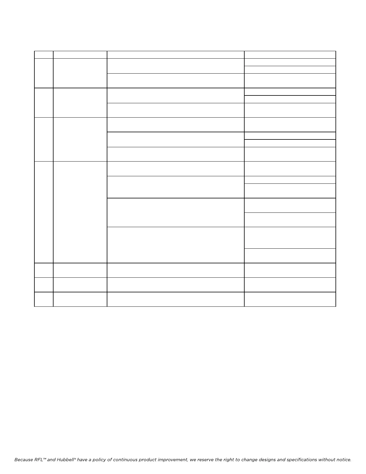
Table 1. Controls and indicators, RFL VF-10D Foreign Exchange Voice Module
Item Name/Description Function Setting
1 DIP switch SW1 SW1-1 Sets chan 1 for loop start or ground start UP: Ground Start
DOWN: Loop Start
(SW1-2 Sets chan 1 TX circuit audio level
thru -8)
See Table 3
2 DIP switch SW2 SW2-1 Enables/Disables chan 1 signaling delay UP: Signaling delay disabled
DOWN: Signaling delay enabled
(SW2-2 Sets chan 1 RX circuit audio level
thru -8)
See Table 3
3 DIP Switch SW9 (SW9-1 Selects the SCB address See Table 2
thru -6)
SW9-7 Selects Normal or Enhanced mode UP: Enhanced Mode
DOWN: Normal Mode
SW9-8 Enables or Disables Channel 2 DOWN: Channel 2 Disabled *
4 DIP Switch SW10 (SW10-1 Time Slot Select
thru -5)
See Table 4
SW10-6 Selects bus transmit direction UP: “B” direction (D&I only)
DOWN: “A” direction (required
for terminal multiplexer)
SW10-7 Selects Local or Remote control UP: Local control
(using switches)
DOWN: Remote Control
(over SCB)
SW10-8 Turns module service ON or OFF UP: Service ON
(over-ridden if
improperly configured)
DOWN: Service OFF
5 LED Indicator DS1 Lights when the line connected to Chan 1 is ringing
NA
6 LED Indicator DS2 Lights when the line connected to Chan 1 is busy
(in use)
NA
7 LED Indicator DS5 Lights when the modules service is enabled
NA
* Channel 2 is always set to disabled.