Because RFL™ and Hubbell® have a policy of continuous product improvement, we reserve the right to change designs and specifications without notice.
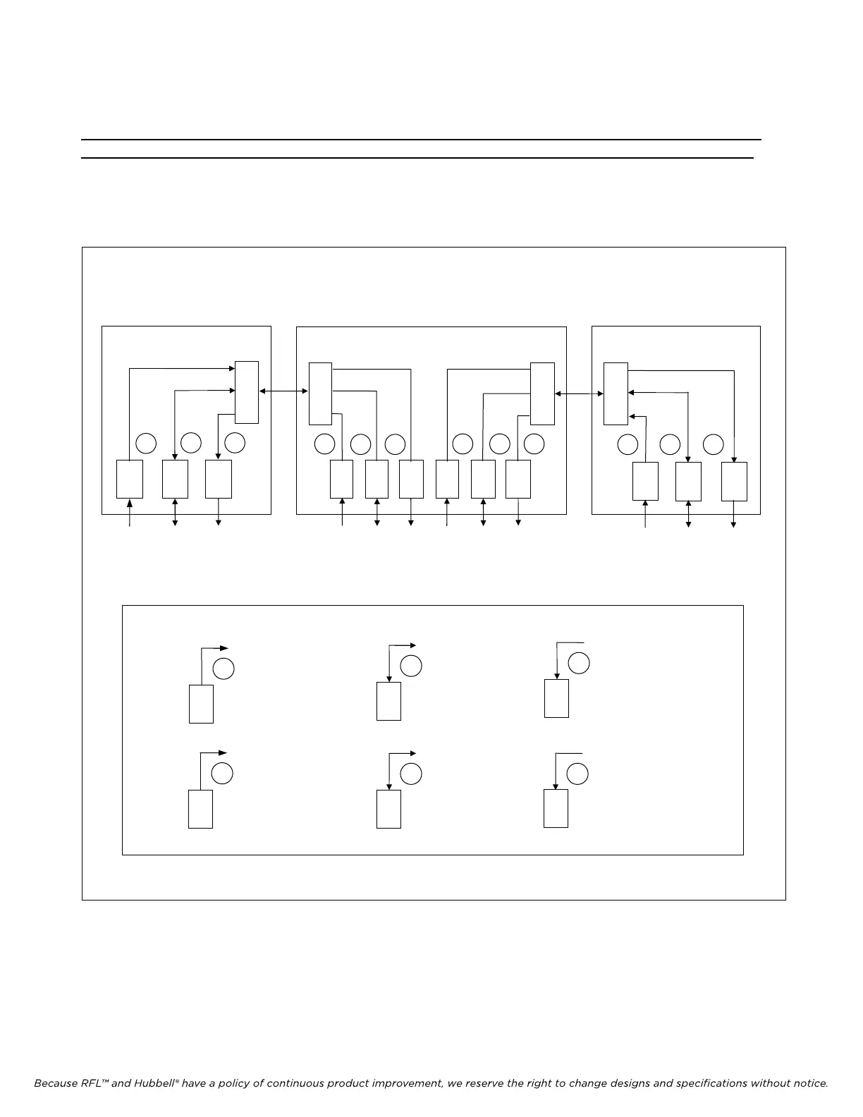
Figure 4-2 further illustrates this subject by showing multiple channel modules of various types in a
three-node system, using both terminal and drop/insert multiplexers. It is important to note that
channel module direction does not correspond to a particular geographic direction (such as east or
west), or to a particular topological direction (such as towards Location 1 or towards Location 2).
For example, in Figure 4-2, the transmit-receive (T/R) and transmit-only (T) channel modules in
multipleers #1 and #2 that are configured to transmit in the “A” direction, actually transmit in opposite
directions over the same E1 facility.
KEY:
T
T/R
R
T/R
R
A
A
A
B
B
T
B
Transmit-only module
Direction = A
Transmit-only m
odule
Direction = B
Transmit/Receive module
Direction = A
Receive-only module
Direction = A
Transmit/Receive module
Direction = B
Receive-only module
Direction = B
C
M
3
C
M
3
C
M
3
C
M
3
T
T/R
R
T
T/R
R
T
T/R
R
T
T/R
R
A A B
A
A B
B B
A
PAYLOAD CIRCUITS
PAYLOAD CIRCUITS
PAY
LOAD CIRCUITS
IMUX 2000
TERMINAL MULTIPLEXER #1
IMUX 2000
TERMINAL MU
LTIPLEXER #2
IMUX 2000
DROP/I
NSERT MULTIPLEXER #2
TERM
DI-A
DI-B
TERM
E1
E1
A
A
B
Figure 4-2. Channel direction setup for transmit-only, transmit/receive, and receive-only channel modules
IMUX 2000E1 RFL Electronics Inc.
January 1, 2008 4-4 (973) 334-3100
 Loading...
