Do you have a question about the Ricoh aficio 1013F and is the answer not in the manual?
Specifies environmental, power, and space requirements for machine installation.
Details installation and setup procedures for the copier unit.
Covers accessory check and installation for the paper tray unit.
Details accessory check and installation for the paper tray unit heater.
Covers accessory check and installation procedures for the document feeder.
Details the installation procedure for the DIMM memory module.
Provides tables detailing preventive maintenance tasks, intervals, and actions for components.
Explains the procedure to reset the PM counter after maintenance is completed.
Lists general precautions and specific warnings before performing replacement or adjustment procedures.
Lists special tools and lubricants required for maintenance and replacement.
Details procedures for removing and replacing exterior covers and the operation panel.
Describes scanner unit components and replacement procedures.
Covers the fusing unit, its components, and related replacement procedures.
Details procedures for replacing the Photoconductor Unit (PCU).
Explains removal and replacement of the toner supply clutch.
Describes paper feed system components and replacement procedures.
Covers image transfer roller and ID sensor replacement procedures.
Details the procedure for replacing the Function Control Unit (FCU).
Covers the laser unit, its components, and related safety precautions.
Describes procedures for replacing various other components.
Explains adjustments for print and scan image quality.
Lists service call conditions, their definitions, and reset procedures.
Provides a detailed list of SC codes, symptoms, and possible causes.
Details common electrical component errors and their symptoms.
Lists fuse types, ratings, and conditions where fuses might blow.
Explains how to extract fuser temperature logs for analysis.
Explains how to access and use the Service Program (SP) mode for diagnostics and adjustments.
Lists and describes various Service Program (SP) modes for machine adjustments.
Details how to print various test patterns for calibration and diagnosis.
Explains how to check sensor and switch status using the input check function.
Details how to check the operation of electrical components using the output check function.
Explains how to print SMC reports containing machine data and settings.
Describes how to reset all SP/UP settings to factory defaults.
Explains how to upload or download machine firmware using a flash memory card.
Details how to save and restore machine settings using SRAM and a flash memory card.
Explains how to input the machine's serial number.
Provides guidance on analyzing ID sensor errors to improve image quality.
Explains how to read and write data to arbitrary RAM addresses.
Describes how users can access and change machine settings via User Tools.
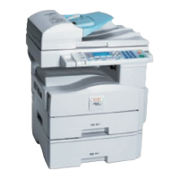
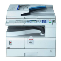
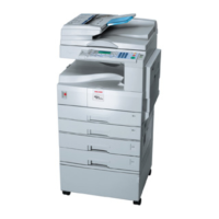
Provides a general overview and component layout of the machine.
Illustrates and describes the path paper takes through the machine.
Shows the layout of various drive components and motors within the machine.
Presents a block diagram of the machine's PCBs and interconnected components.
Details the main Printed Circuit Boards (PCBs) and their functions.
Provides a step-by-step overview of the copying process.
Describes the scanning process, including component overviews.
Explains the image processing steps and modules used in the machine.
Details the laser exposure unit and its overview.
Provides an overview of the Photoconductor Unit (PCU) components.
Explains the drum charging process and voltage correction.
Describes the development section components and toner density control.
Explains the process of cleaning the drum and recycling toner.
Details the paper feed system overview and mechanisms.
Covers the image transfer process and paper separation.
Describes the image fusing unit and paper exit area.
Explains the machine's energy-saving modes and transitions.
Provides general technical specifications for the machine.
Lists the available features of the machine.
Details the system components and machine configuration.
Explains the flow of video data for transmission and reception.
Provides general information including mechanical, electrical, and drive layouts.
Details pick-up, separation, clutch operation, transport, exit, and electrical circuits.
Covers procedures for replacing DF covers, table, feed unit, rollers, motor, clutch, sensors, and connection board.
Covers machine information including mechanical, electrical, drive layouts, and circuits.
Details paper feed, separation, lift mechanism, end detection, and side/end fences.
Covers replacement of feed roller, friction pad, and removal of the paper tray unit.
Covers installation requirements, fax unit setup, and handset installation.
Details special tools, lubricants, and PM tables for the fax unit.
Covers precautions and procedures for replacing FCU, NCU, and monitor speaker.
Lists error codes and fax-specific SC codes for troubleshooting.
Explains service level functions, bit switches, NCU parameters, and dedicated transmission parameters.
Covers installation requirements and printer installation procedures.
Lists controller error codes and LED display indicators for troubleshooting.
Explains service program mode, service menu, and diagnostic procedures.
Describes controller functions, block diagrams, and system components.
Lists general specifications, supported paper sizes, and software accessories.
| Functions | Print, Copy, Scan, Fax |
|---|---|
| Print Technology | Laser |
| Print Speed | 13 ppm |
| Print Resolution | 600 x 600 dpi |
| Copy Speed | 13 cpm |
| Copy Resolution | 600 x 600 dpi |
| Scan Resolution | 600 x 600 dpi |
| Scanner Type | Flatbed |
| Fax Speed | 33.6 kbps |
| Modem Speed | 33.6 kbps |
| Monthly Duty Cycle | 10, 000 pages |
| Paper Capacity | 250 sheets |
| Zoom | 25% - 400% |
| Supported Operating Systems | Windows, Mac OS |
| Paper Size | A4 |
| Interface | USB 2.0 |