bars).
7. Remedy any leaky couplings or other leaks.
The unit will automatically vent air through the air bleed valve. It is normal
for some water to run out of the tube attached to the air bleed valve.
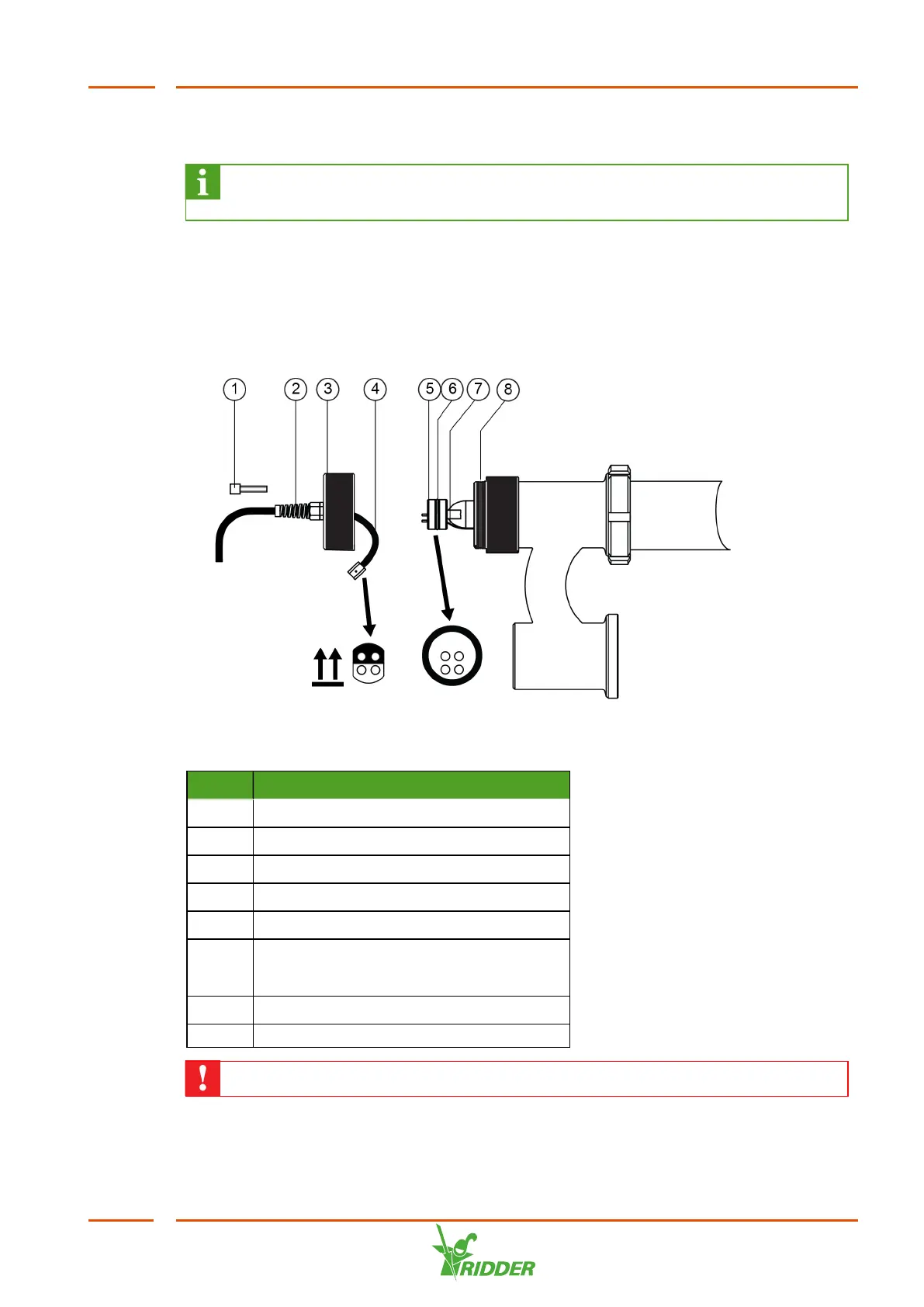
4.7.4 Installing UV-C lamps
Once you have made sure that the unit is not leaking, you can install the lamps. The
lamps are numbered in order of flow: lamp 1 is located where the water enters the
lamp section.
Figure 4-12: Installing UV-C lamp
No. Description
1 M4 socket screw
2 Strain relief cable gland
3 Reactor cap
4 Connectors
5 UV-C lamp
6 Ø 44 mm quartz tube: O-ring 32 x 3 mm
Ø 55 mm quartz tube: O-ring 32 x 7 mm
7 Lamp wires on the underside
8 O-ring for UV reactor plug
Only handle lamps with the gloves provided.
VitaLite
37