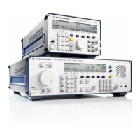
V L F > H F R E C E I V E R S
f
R & S E K 8 9 5 / R & S E K 8 9 6
User Manual
List of Figures
Fig. Title Page
4.1 Test Setup . . . . . . . . . . . . . . . . . . . . . . . . . . . . . . . . . . . . . . . . . . . . . 4.21
4.2 Location of Connector X20 (Control Unit 1) . . . . . . . . . . . . . . . 4.23
4.3 Location of Connector X20 (Control Unit 2) . . . . . . . . . . . . . . . 4.24
4.4 Location of Connectors X5 and X20 (Control Unit) . . . . . . . . . 4.25
4.5 Location of Back>up Battery . . . . . . . . . . . . . . . . . . . . . . . . . . . . . 4.26
4.6 Location of Screws . . . . . . . . . . . . . . . . . . . . . . . . . . . . . . . . . . . . . 4.29
4.7 Location of Terminal Strips X77 and X78 . . . . . . . . . . . . . . . . . . 4.34
4.8 Location of Screws to Be Undone on Front (R&S EK 895) . . . . 4.37
4.9 Location of Screws to Be Undone on Front (R&S EK 896) . . . . 4.39
4.10 Location of Screws to Be Undone on Rear (R&S EK 895) . . . . 4.41
4.11 Location of Screws to Be Undone on Rear (R&S EK 896) . . . . 4.43
4.12 Arrangement of Modules and Options (R&S EK 895) . . . . . . . 4.45
4.13 Arrangement of Modules and Options (R&S EK 896) . . . . . . . 4.47
4.14 Internal Cabling . . . . . . . . . . . . . . . . . . . . . . . . . . . . . . . . . . . . . . . . 4.49
4.15 Internal Cabling (with Options) . . . . . . . . . . . . . . . . . . . . . . . . . . 4.51
4.16 Removal of Digitally Tuned RF Selector R&S FK 896 (Option) 4.53
4.17 Cabling of VLF>HF Receiver R&S EK 896 with
Digitally Tuned RF Selector FK 896D (Option) . . . . . . . . . . . . . 4.55
6164.0717.02_01
> 04.3 / 04.4 >

 Loading...