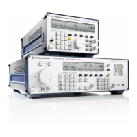
V L F > H F R E C E I V E R S
f
R & S E K 8 9 5 / R & S E K 8 9 6
User Manual
f
Replacement of Modules
4.3 Replacement of Modules
4.3.1 Preparations
1. Switch off VLF>HF receiver.
Æ LED POWER is dark
(control unit 2 ∫LOCAL∫ (R&S EK!895, = op>
tion 'Control Unit R&S GB 890') or control
unit (R&S EK!896)).
POWER
Æ LED ON is dark
(control unit 1 ∫REMOTE∫ (R&S EK!895))
EIN
.
ON
2. Disconnect mains cable from plug X67.
3. Undo and remove four screws (1, Fig. 4.10
(R&S EK!895) or Fig. 4.11 (R&S EK!896)) fix>
ing the rear panel stands.
4. Remove rear panel stands.
5. By means of a screw driver remove top and
bottom hoods.
6. After replacement of modules proceed in
the reverse order of steps 3 to 5.
6164.0717.02_01
> 4.22 >

 Loading...