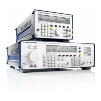
V L F > H F R E C E I V E R S
f
R & S E K 8 9 5 / R & S E K 8 9 6
User Manual
f
Application
1.2.3 Functioning
(See Figs. 1.20 and 1.21)
The input signal from the antenna is routed via
the antenna socket at the rear to a lowpass fil>
ter in the HF unit. The filter is used for image
frequency selection and suppression of oscilla>
tor reradiation. Subsequently the signal is ap>
plied to the input mixer where it is converted
to the 1st!IF of 41.44!MHz by means of an oscil>
lator variable in 1>Hz increments.
The crystal filter which follows determines the
maximum receive bandwidth of 10!kHz and
provides for selection of the second image fre>
quency. Conversion to the 2nd IF of 1.44 MHz is
obtained by using a 40>MHz fixed frequency.
A powerful mixer at the receiver input ensures
excellent large>signal behaviour. The intercept
points are typically +70!dBm (IP
2
) and
+35!dBm (IP
3
); with an interfering signal of
+21!dBm the crossmodulation transfer is 10!%.
Therefore in most cases no additional filters
are required.
In the IF / AF processor the 2nd IF is routed via
a filter and then converted to the 3rd IF of
25!kHz by using a 5.66>MHz fixed frequency.
After digitization of the 3rd IF in a 16>bit A/D
converter, the DSP (Digital Signal Processor)
carries out all signal generation and processing
tasks such as:
> Automatic, remote or manual control,
> Measurement of receive levels,
> Filtering with 17 fixed or 128 quasi>
continuously adjustable filter bandwidths
> Demodulation, passband tuning,
double notch filter,
> Noise blanker, syllable squelch,
> Generation of BFO frequency, analog IF
from 0 to 40 kHz and digital IF as serial data
and I/Q data current.
The synthesizer supplies all conversion fre>
quencies required by the HF unit and the IF de>
modulator. By direct digital frequency syn>
thesis the frequency of the first conversion os>
cillator is varied in 1>Hz increments. The set>
tling time of the oscillator is 5!ms with any fre>
quency variation. Two phase>locked loops
(PLLs) generate the fixed frequencies of
40!MHz and 5.66!MHz. The operation of the
total of four PLLs in the synthesizer is continu>
ously monitored.
In the basic version, all frequencies are derived
from a temperature>compensated crystal oscil>
lator. Higher precision requirements can be
met by integrating an optional oven>
controlled crystal oscillator or by using an ex>
ternal frequency standard.
The processor is made up of a modern 16>bit>
microprocessor in CMOS technology. It not
only provides for control and management of
the individual modules, but also communicates
via the front panel and the data interface with
the outside world and executes the internal
programs. The following routines increase the
operational reliability:
> Non>volatile storage of all settings
> Continuous monitoring of CPU, RAM and
PROM functions
> Continuous monitoring of synthesizer (CM)
> Built>in test (BIT) for module testing
Local control of the receiver (R&S EK 895, Mod.
12 / R&S EK!896) takes place via the control and
display elements of the control unit (A2).
Remote control is also possible.
Remote control via ASCII commands (e.g. R&S
EK!895, Mod. 02) takes place via a multi>
standard interface (RS!232C, RS!485, RS!422 /
423). In the simplest case a terminal can be
used as control unit, more complex functions
can be handled by a Personal Computer.
6164.0717.02_01
> 1.6 >

 Loading...