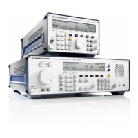
V L F > H F R E C E I V E R S
f
R & S E K 8 9 5 / R & S E K 8 9 6
User Manual
f
Frame
1.3 Design and Functioning of Modules
1.3.1 Frame
1.3.1.1 Design
The frame consists of a KB 90 housing (see Fig.
1.4), frame accessories, rods for connection to
the power switch and the carrier board (A11).
Fig. 1.4 KB 90 Housing
Part of the frame accessories are for example
the guiding rails, which together with the ex>
tracting levers on the modules guarantee that
the plugs on the modules and the sockets on
the carrier board engage correctly.
The carrier board accommodates the female
connector strips and is connected to the power
supply and the control unit via ribbon cables.
1.3.1.2 Functioning
(See circuit diagrams 6057.8996.01S, sheet 2
(=!R&S EK!895) and 6038.2509.01S, sheet 2
(=!R&S EK!896) appended to this section 1)
The carrier board interconnects all modules
and supplies them with the following signals
and voltages:
f AF signals
(AF, AFL, AF option, AF Out)
f Demodulation signals
(sign, FSK>TTL, F6>V28, FSK>V28, FM>Video,
FAX a, FAX b, FSK)
f Control and status signals
(Read, Write, LED0 to LED4, PZG1 to PZG3,
RESET, Stop, Inhibit, IRQCM, IRQF, CM
Mains, TxD, RxD, RTS, RxC, CTS, DSR, DTR)
f Address, data and CS bits
(MD0 to MD15, MS0A to MS3A, MS0B to
MS3B, MS0C to MS3C, MAD0 to MAD2)
f Voltages
(+15 V, >15 V, +5 V, +3.0 V, +3.75 V,
MGC, AGC, DGC)
6164.0717.02_01
> 1.7 >

 Loading...