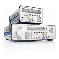
V L F > H F R E C E I V E R S
f
R & S E K 8 9 5 / R & S E K 8 9 6
User Manual
f
Application
1.2.2 Design of VLF>HF Receiver R&S EK 896
The VLF>HF Receiver R&S EK 896 is accommo>
dated in a case of the R&S Series KB90. The case
has approx. the entire width of a standard 19∫
slide>in unit.
The receiver is designed as a desk>top unit. The
use of a special 19∫ adapter, however, also per>
mits its installation into a 19∫ rack.
At the bottom of the case four sturdy equip>
ment stands are located. The two front stands
are designed to be set up, so that the receiver
front part can be raised. This makes for better
readability of the displays and improves the
operating ease.
At the front of the case a front panel is located.
Depending on the respective receiver design,
the front panel accommodates various control
and display elements for local control or only
LED status indicators for mere remote control.
The front panel for local control contains a
graphic display, several separate keys and key
pads as well as a highly sensitive tuning knob
and so>called softkeys.
As a function of the operating mode and the
operational requirements, different functions
can be assigned to the tuning knob. It is for in>
stance possible to adjust the receive frequency
digitally via the numeric keypad and also quasi>
analogously via the tuning knob.
Another specialty are the so>called softkeys.
Depending on the set operating mode and the
relevant operating level, these keys handle
different functions. The currently active
function is indicated in plain text in the display
box directly above the relevant key.
One half of the rear panel of the case is mainly
formed by a heat sink for the integrated power
supply unit. This part also accommodates the
external interface connectors and a mains
voltage selector.
This rear panel part is nearly identical with the
R&S EK!895 rear panel. The other half of the
rear panel only carries an additional head>
phone interface connector.
Also located at the rear are two supportive ele>
ments preventing damages to the connectors
in case the equipment is put down on its rear
panel.
The case accommodates the following modules
which form the actual receiver:
f
A1 Frame
f
A2 Control Unit
f
A3 Processor
f
A4 Synthesizer
f
A5 HF Unit
f
A6 Power Supply
f
A7 IF / AF Processor
Further the receiver comprises top and bottom
panelling as well as an RF cable set.
Except for the power supply, all modules are
designed as plug>in devices with extracting
levers. This offers high ease of replacement
even in the maximum configuration where
modules are installed very close to each other.
In addition to the standard modules listed
above, two plug>in slots for extensions are
available with complete cabling and connec>
tion to the internal control bus.
For special applications the following modules
can be provided as options:
f
Preselection R&S FK 890H1
f
BCD Interface R&S GC 890
f
TTY Line Current Source R&S GH 890
f
IF Converter R&S UX 895
f
IF Processor R&S GM 893
f
Digitally Tuned RF
Selector 20 or 40 dB R&S FK 896D
6164.0717.02_01
> 1.4 >

 Loading...