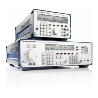
V L F > H F R E C E I V E R S
f
R & S E K 8 9 5 / R & S E K 8 9 6
User Manual
f
External Interfaces
A2. External Interfaces
(See Fig. A2.2 for VLF>HF Receiver EK 895 and Fig. A2.3 for VLF>HF Receiver EK 896)
A2.1 Headphone Connection (EK 896, Rear)
Recessed jack>type socket,
2>way
(FT 019.0493)
Signal designation / level
AF OUT (AF output) /
P
max
= 1 ±0.2 W, R
l
= 8 ] at f = 1 kHz
Contact
Mating connector:
6.3>mm jack>type plug, 2>way
(FT 019.0487)
A2.2 Antenna Connection
Recessed RF socket, system BNC
(FJ 017.6636)
Signal designation / level
ANT (antenna input) / max. permissible input
voltage 15 V
EMF
(e 30 MHz),
R
i
= 50 ], VSWR < 3
Contact
Mating connector:
Cable plug, straight,
system BNC
(FJ 075.8421)
Recommended cable
DH 025.2142
6164.0717.02_01
> A2.1 >

 Loading...