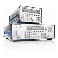
V L F > H F R E C E I V E R S
f
R & S E K 8 9 5 / R & S E K 8 9 6
User Manual
f
Control Unit 2 ∫LOCAL∫
1.3.3 Control Unit 2 ∫LOCAL∫ (R&S EK 895, =
Option 'Control Unit R&S GB 890')
1.3.3.1 Design
The control unit consists of a mounting plate, a
logic circuit (A2.1) a keyboard (A2.2), a display
(A2.3), and a recessed jack>type socket.
The logic circuit contains the interfaces to the
carrier board as well as to the keyboard and
the display.
1.3.3.2 Functioning
(See Fig. 1.6)
The internal processes within the key decoder
are derived from a 4>MHz quartz oscillator.
The key decoder continuously monitors the key
matrix and the tuning knob. For this purpose, a
sampling signal is sent out in turns via the
sampling lines. If a key is activated, the samp>
ling pulse returns via the respective line to the
key decoder. The tuning knob consists of an
angular>momentum generator (24 steps / re>
volution) and two Hall probes (= pulse re>
ceivers). As a result of the rotation of the
angular>momentum generator, pulses are pro>
duced in the Hall probes, which are evaluated
by the key decoder.
As soon as the key decoder receives a sampling
pulse or pulses from the Hall probes, the re>
spective message is sent via interrupt line IRQF
to the CPU in the processor. As a reaction, the
CPU inquires via the data bus the 8>bit data
item from the key decoder. The data item con>
tains the information which key or softkey was
actuated or by how many increments the tun>
ing knob was turned clockwise or counter>
clockwise.
The information is processed within the CPU. If
the operator activates for example the BFO
key, the LED BFO will light up and the display
will change. Instead of the modulation type,
type and time of control as well as the softkey
assignment, the display BFO_ kHz and the
cursor appear in the BFO field. For this change
on the display, the CPU sends 8>bit data items
via the data bus to the LCD drivers and an in>
termediate memory. Which driver becomes ef>
fective upon which data item, is selected by the
CPU via the 8>out>of>3 converter.
The signal CM MAINS provided by the monitor>
ing circuit in the the power supply drives a
green LED. Illumination of this LED will indi>
cate that the power supply is working properly.
By means of the HF control the control voltage
for manual gain control may be adjusted. The
MGC voltage is routed to the control loop in
the IF / AF processor.
The AF signal AFL produced through demodu>
lation in the IF / AF processor is amplified by
the AF amplifier, the gain being adjustable by
means of the AF control. Through headphones
or a loudspeaker to be connected the AF signal
can be made audible.
6164.0717.02_01
> 1.10 >

 Loading...