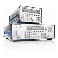
V L F > H F R E C E I V E R S
f
R & S E K 8 9 5 / R & S E K 8 9 6
User Manual
f
Synthesizer
1.3.6 Synthesizer
1.3.6.1 Design
The synthesizer consists of a printed circuit
board, a set of screens, two RF covers, two blue
extracting levers, the EPROM program set
(A41), the interface to the carrier board as well
as HF interfaces. Via the HF interfaces and
cables contained in the cable set, the
synthesizer is connected to the rear panel, the
HF unit and the IF / AF processor.
The synthesizer contains jumpers for switch>
over between internal and external synchro>
nization and for setting the division ratio (1:1,
5:1 or 10:1).
1.3.6.2 Functioning
(See Fig. 1.9)
All frequencies generated in the synthesizer
are derived from a 10>MHz crystal oscillator
(TCXO, mod. 02) or a 10>MHz oven controlled
crystal oscillator (OCXO, mod. 03).
The crystal oscillator can also be substituted by
an external frequency standard (direction>
finding applications, higher precision). For this
purpose the jumper for internal/external
switchover must be set to external. Depending
on the frequency standard used, the required
division ratio 10:1 for f
ext.
= 10 MHz and
internal synchronization, 5:1 for f
ext.
= 5 MHz
or 1:1 for f
ext.
= 1 MHz is to be set via jumpers
in the divider switchover circuit.
In the logic circuit the digital frequency in>
formation from the processor is split up into
two information blocks, the first block con>
taining the 100>kHz, 1>MHz and 10>MHz po>
sitions and the second one the positions 1 Hz to
10 kHz. The sum of the first block and the
number 413 (41.3 MHz) gives the division ratio
N = 413 to 713 for the 1:N divider in phase>
locked loop 2. The preset VCO2 thus oscillates
on a frequency of f
VCO2
= N¥1:10¥1 MHz=
41.3 to 71.3 MHz. The output signals of VCO2
and of preset VCO3 are converted in the
conversion stage into a signal with a frequency
of f
2
= f
VCO3
> f
VCO2
. The phase regulator z3
regulates to the phase difference between the
frequency f
2
and the frequency (f
synthesis
) of
the output signal of the analog/digital con>
verter.
For this the EPROM (stored sine table) is con>
trolled by the logic circuit in such a way that on
the output of the buffer a digital sinusoidal
signal is produced (DDS, direct digital syn>
thesis). The frequency of the sinusoidal signal
results from the sum of the second block and
the number 140000 (140 kHz). Therefore VCO3
oscillates on a frequency of f
VCO3
=f
VCO2
+
f
synthesis
= 41.44 to 71.44 MHz. The signal
generated by phase>locked loop 3 is fed to the
1st>IF converter stage in the HF unit.
The frequency on which VCO1 oscillates is de>
termined by the division ratio of the two fre>
quency dividers and the reference signal Æ
f
VCO1
= 4:1 ¥ 10:1 ¥ 1 MHz = 40 MHz. The
signal generated by phase>locked loop 1 is
transferred to the 2nd>IF converter stage in the
HF unit and to the IF / AF processor.
The frequency on which the VCO4 oscillates is
determined by the 875:1 divider, the converter
stage, and the f
1
signal as follows:
Æf
VCO4
= 875:1 ¥ f
1
+ 10 MHz
Æf
1
= 40 MHz¥1:4¥1:26¥1:625 = 640 Hz
Æf
VCO4
= 10.56 MHz
The signal synchronized by phase>locked loop 4
is fed via a frequency divider with the division
ratio 1:8 to the converter stage. The converter
stage is followed by a selective amplifier for
suppression of unwanted mixing products and
another frequency divider. The 5.66>MHz
signal thus generated is routed to the IF / AF
processor.
In case of a test, the 1>MHz signal is fed via a
10:1 divider into the receive path.
In the CM test the phase>locked loops and the
2:1 divider level are continuously monitored. If
the level falls below a minimum value and/or if
a phase>locked loop is not synchronized, this
information is transmitted in the form of an
'interrupt' via the IRQCM line to the processor.
Via line CM SYNTH, the processor can inquire
the CM status.
6164.0717.02_01
> 1.16 >

 Loading...