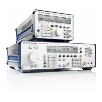
V L F > H F R E C E I V E R S
f
R & S E K 8 9 5 / R & S E K 8 9 6
User Manual
f
HF Unit
1.3.7 HF Unit
1.3.7.1 Design
The HF unit consists of a printed circuit board, a
set of screens, two RF covers, two green extrac>
ting levers, a transformer board (A51), the in>
terface to the carrier board and HF interfaces.
Via the HF interfaces and cables contained in
the cable set, the HF unit is connected to the
rear panel, the synthesizer and the IF / AF pro>
cessor.
1.3.7.2 Functioning
(See Fig. 1.10)
Depending on the position of the switch,
either the HF signal (ANT, 10 kHz to 30!MHz)
from the IF / AF processor or the 100>kHz test
signal (TESTSIG) is routed from the synthesizer
via a lowpass filter to the 1st converter stage.
By means of the adjustable attenuator, the test
signal is attenuated. The attenuation factor as
well as selection of the signal to be transmitted
to the converter stage are controlled by the
processor via two signal lines (attenuation,
test). The lowpass filter provides for sup>
pression of image frequencies and oscillator
reradiation.
In the 1st converter stage, the antenna signal is
mixed with the oscillator frequency adjustable
in 1>Hz increments and supplied by the synthe>
sizer to form the first intermediate frequency
of 41.44 MHz. The following crystal filter sup>
presses the 2nd image frequency and fixes the
maximum receive bandwidth to 8.0 kHz.
The 41.44>MHz signal is fed via the controllable
amplifier to the 2nd converter stage.
In the 2nd converter stage the 41.44>MHz sig>
nal is mixed with the 40>MHz fixed frequency
from the synthesizer to form the 2nd inter>
mediate frequency of 1.44 MHz. The following
IF amplifier provides the IF2 signal for the IF /
AF processor and another signal for the recti>
fier.
In transmit/receive operation, the IF amplifier
can be inhibited via the signal Inhibit.
The rectifier supplies the BIT signal and the
control voltage for the controllable amplifier.
Via an adder, to this control voltage the con>
trol voltage from the IF / AF processor (AGC HF)
is added. Thus overloading is prevented.
In case the built>in equipment test is initiated,
the processor also inquires the status of the BIT
signal from the HF unit.
6164.0717.02_01
> 1.18 >

 Loading...