Configuration Guide Configuring ACL
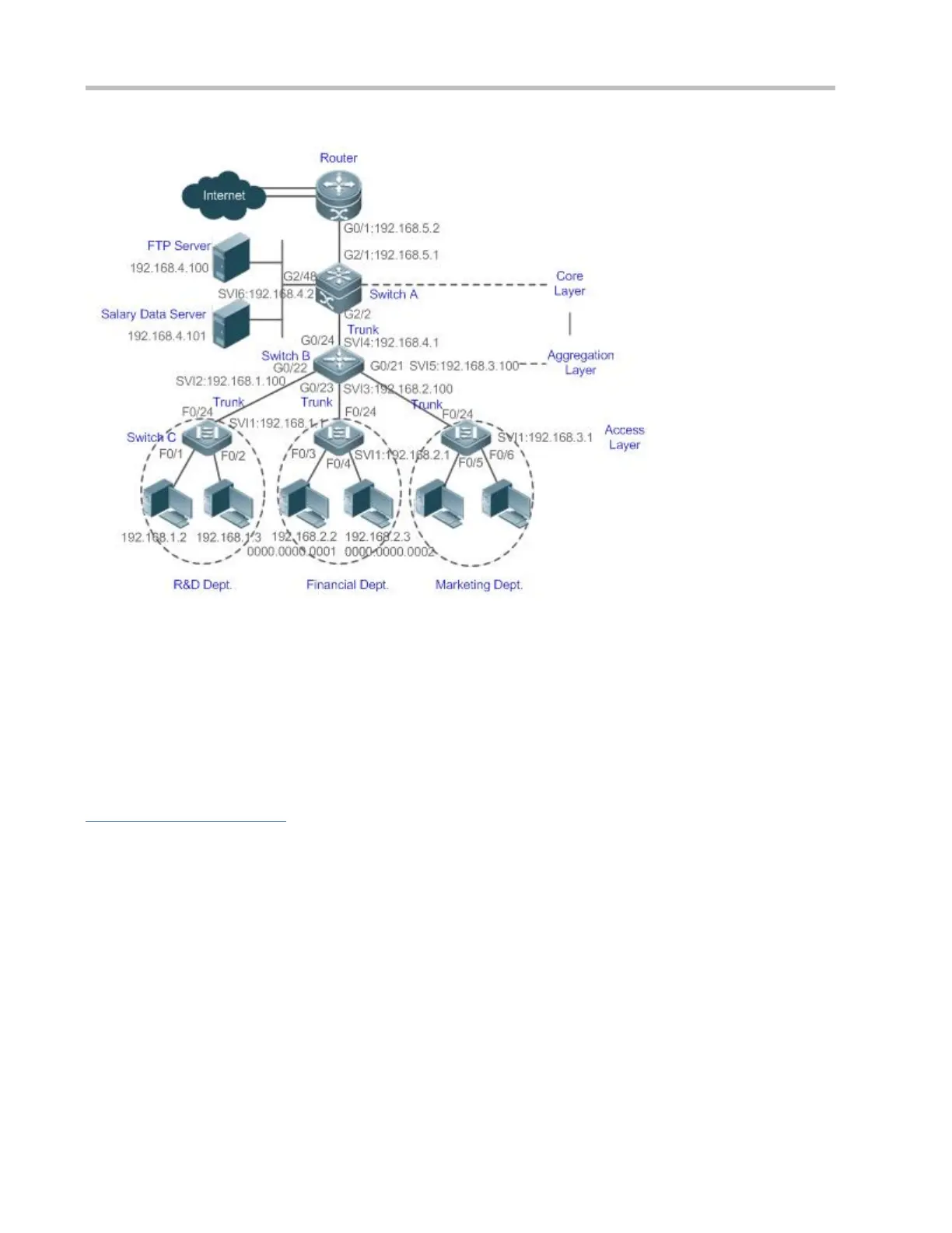
Switch C at the access layer:It is connected to PCs of each department and to Switch B at the aggregation layer
through the gigabit optical fiber (trunk mode).
Switch B at the aggregation layer:Multiple virtual local area networks (VLANs) are divided. One VLAN is defined
for one department. These VLANs are connected to Switch A at the core layer through the 10-gigabit optical fiber
(trunk mode).
Switch A at the core layer:It is connected to various servers, such as the File Transfer Protocol (FTP) server and
Hypertext Transfer Protocol (HTTP) server, and to the Internet through firewalls.
Deployment
Configure an extended ACL on the port G2/1 to filter data packets, thus protecting the network against the viruses. This
port is located on a core-layer device (Switch A) and used to connect Switch A to the uplink port G2/1 of a router.
Allow only internal PCs to access servers, and prohibit external PCs from accessing servers. Define and apply the
extended IP ACLs on G2/2 or switch virtual interface (SVI) 2 that is used to connect Switch A to an aggregation layer
device or server.
Prohibit mutual access between specified departments. Define and apply the extended IP ACLs on G0/22 and G0/23 of
Switch B.
Configure and apply the time-based extended IP ACLs on SVI 2 of Switch B to prohibit the R&D department from using
chatting tools (such as QQ and MSN) in a specified period of time.
 Loading...