SETTINGS SHEET Page 18 of 24
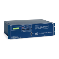
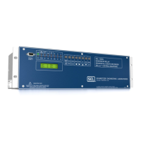
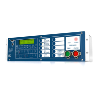
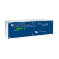
FOR THE SEL-351 RELAY Date
SELOGIC CONTROL EQUATION SETTINGS (SERIAL PORT COMMAND SET L)
Date Code 20001006
Setting Group Selection Equations (See Table 7.4)
Select Setting Group 1 SS1 =
Select Setting Group 2 SS2 =
Select Setting Group 3 SS3 =
Select Setting Group 4 SS4 =
Select Setting Group 5 SS5 =
Select Setting Group 6 SS6 =
Other Equations
Event report trigger conditions (see Section 12) ER =
Fault indication [used in INST, A, B, and C target logic
(see Table 5.1); used also to suspend demand metering
updating and peak recording and block max./min.
metering (see Demand Metering and
Maximum/Minimum Metering in Section 8)]
FAULT =
Block synchronism check elements (see Figure 3.26) BSYNCH =
Close bus monitor (see Figure 5.3) CLMON =
Breaker monitor initiation (see Figure 8.3) BKMON =
Enable for zero-sequence voltage-polarized and channel
IN current-polarized directional elements (see Figure 4.6)
E32IV =
MIRRORED BITS™ Transmit Equations (Available in Firmware Versions 1 and Greater;
see Appendix I)
Channel A, transmit bit 1 TMB1A =
Channel A, transmit bit 2 TMB2A =
Channel A, transmit bit 3 TMB3A =
Channel A, transmit bit 4 TMB4A =
Channel A, transmit bit 5 TMB5A =
Channel A, transmit bit 6 TMB6A =
Channel A, transmit bit 7 TMB7A =
Channel A, transmit bit 8 TMB8A =
Channel B, transmit bit 1 TMB1B =
Channel B, transmit bit 2 TMB2B =
Channel B, transmit bit 3 TMB3B =
Channel B, transmit bit 4 TMB4B =
Channel B, transmit bit 5 TMB5B =
Channel B, transmit bit 6 TMB6B =
Channel B, transmit bit 7 TMB7B =
Channel B, transmit bit 8 TMB8B =
Courtesy of NationalSwitchgear.com


 To Next Page