Date Code 20001006 Distributed Network Protocol (DNP) V3.00 H-11
SEL-351 Instruction Manual
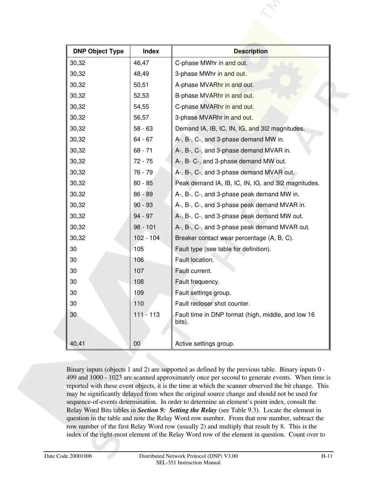
DNP Object Type Index Description
30,32 46,47 C-phase MWhr in and out.
30,32 48,49 3-phase MWhr in and out.
30,32 50,51 A-phase MVARhr in and out.
30,32 52,53 B-phase MVARhr in and out.
30,32 54,55 C-phase MVARhr in and out.
30,32 56,57 3-phase MVARhr in and out.
30,32 58 - 63 Demand IA, IB, IC, IN, IG, and 3I2 magnitudes.
30,32 64 - 67 A-, B-, C-, and 3-phase demand MW in.
30,32 68 - 71 A-, B-, C-, and 3-phase demand MVAR in.
30,32 72 - 75 A-, B- C-, and 3-phase demand MW out.
30,32 76 - 79 A-, B-, C-, and 3-phase demand MVAR out.
30,32 80 - 85 Peak demand IA, IB, IC, IN, IG, and 3I2 magnitudes.
30,32 86 - 89 A-, B-, C-, and 3-phase peak demand MW in.
30,32 90 - 93 A-, B-, C-, and 3-phase peak demand MVAR in.
30,32 94 - 97 A-, B-, C-, and 3-phase peak demand MW out.
30,32 98 - 101 A-, B-, C-, and 3-phase peak demand MVAR out.
30,32 102 - 104 Breaker contact wear percentage (A, B, C).
30 105 Fault type (see table for definition).
30 106 Fault location.
30 107 Fault current.
30 108 Fault frequency.
30 109 Fault settings group.
30 110 Fault recloser shot counter.
30 111 - 113 Fault time in DNP format (high, middle, and low 16
bits).
40,41 00 Active settings group.
Binary inputs (objects 1 and 2) are supported as defined by the previous table. Binary inputs 0 -
499 and 1000 - 1023 are scanned approximately once per second to generate events. When time is
reported with these event objects, it is the time at which the scanner observed the bit change. This
may be significantly delayed from when the original source change and should not be used for
sequence-of-events determination. In order to determine an element’s point index, consult the
Relay Word Bits tables in Section 9: Setting the Relay (see Table 9.3). Locate the element in
question in the table and note the Relay Word row number. From that row number, subtract the
row number of the first Relay Word row (usually 2) and multiply that result by 8. This is the
index of the right-most element of the Relay Word row of the element in question. Count over to
Courtesy of NationalSwitchgear.com



 To Next Page