Date Code 20001006 Installation 2-31
SEL-351 Instruction Manual
The position of the jumper controls the operation of the output contact next to the dedicated
ALARM output contact. With the jumper in one position, the output contact operates regularly.
With the jumper in the other position, the output contact is driven by the same signal that operates
the dedicated ALARM output contact (see Table 2.4 and Table 2.5).
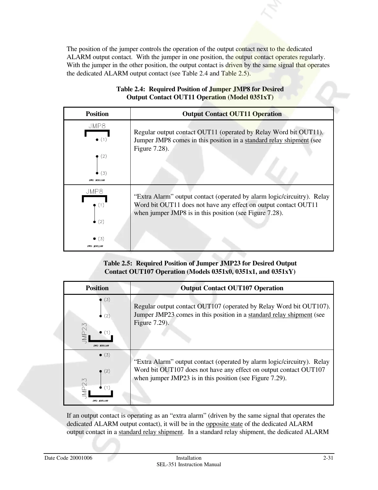
Table 2.4: Required Position of Jumper JMP8 for Desired
Output Contact OUT11 Operation (Model 0351xT)
Position Output Contact OUT11 Operation
Regular output contact OUT11 (operated by Relay Word bit OUT11).
Jumper JMP8 comes in this position in a standard relay shipment (see
Figure 7.28).
“Extra Alarm” output contact (operated by alarm logic/circuitry). Relay
Word bit OUT11 does not have any effect on output contact OUT11
when jumper JMP8 is in this position (see Figure 7.28).
Table 2.5: Required Position of Jumper JMP23 for Desired Output
Contact OUT107 Operation (Models 0351x0, 0351x1, and 0351xY)
Position Output Contact OUT107 Operation
Regular output contact OUT107 (operated by Relay Word bit OUT107).
Jumper JMP23 comes in this position in a standard relay shipment (see
Figure 7.29).
“Extra Alarm” output contact (operated by alarm logic/circuitry). Relay
Word bit OUT107 does not have any effect on output contact OUT107
when jumper JMP23 is in this position (see Figure 7.29).
If an output contact is operating as an “extra alarm” (driven by the same signal that operates the
dedicated ALARM output contact), it will be in the opposite state of the dedicated ALARM
output contact in a standard relay shipment. In a standard relay shipment, the dedicated ALARM
Courtesy of NationalSwitchgear.com