4.36
SEL-749M Relay Instruction Manual Date Code 20080918
Protection and Logic Functions
I/O Configuration
Also note that the relay automatically asserts the trip signal if the motor
stops and a lockout condition is in effect. The trip signal is maintained
until all the enabled motor lockout conditions are satisfied.
52A CONTACTOR/BREAKER STATUS CONDITIONS SEL
OGIC EQUATION
You can connect an auxiliary contact of the contactor or the breaker
to the relay. The SEL
OGIC control equation 52A allows you to
configure the relay for either 52b or 52a contact input (or other
contact that indicates the motor is switched on). The factory-default
setting assumes connection of the 52b contact to input IN101 (see
Figure 2.6 for the input/output connections).
If you do not connect the 52b contact to input IN101, you must change the
factory-default logic equation 52A. For example, set 52A := IN101 if you
connect the 52a contact to input IN101.
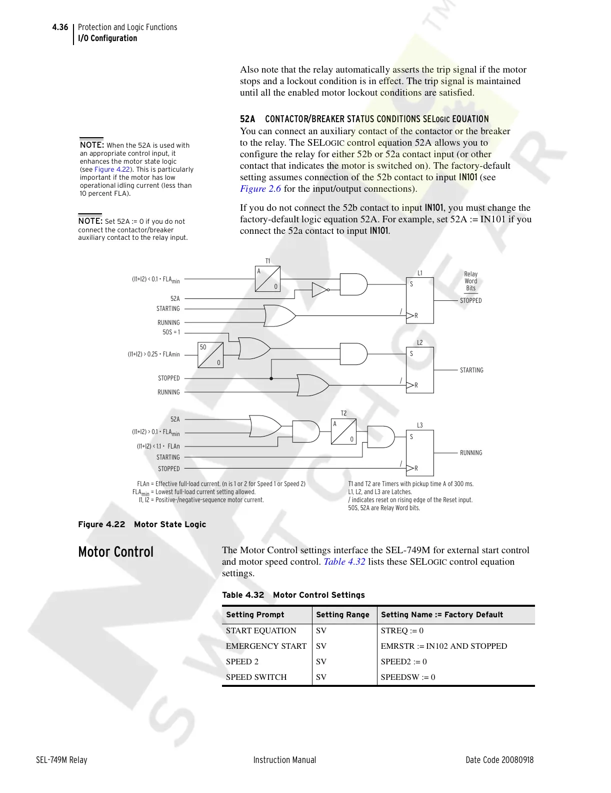
Figure 4.22 Motor State Logic
Motor Control
The Motor Control settings interface the SEL-749M for external start control
and motor speed control. Table 4.32 lists these SEL
OGIC control equation
settings.
NOTE: When the 52A is used with
an appropriate control input, it
enhances the motor state logic
(see Figure 4.22). This is particularly
important if the motor has low
operational idling current (less than
10 percent FLA).
NOTE: Set 52A := 0 if you do not
connect the contactor/breaker
auxiliary contact to the relay input.
A
0
/
STOPPED
(I1+I2) < 0.1 • FLA
min
52A
T1
STARTING
RUNNING
L1
S
R
Relay
Word
Bits
50
0
/
RUNNING
(I1+I2) > 0.1 • FLA
min
(I1+I2) < 1.1 • FLAn
52A
A
0
T2
STARTING
STOPPED
L3
S
R
/
STARTING
(I1+I2) > 0.25 • FLA
min
50S = 1
STOPPED
RUNNING
L2
S
R
FLAn =
FLA
min
=
I1, I2 =
Effective full-load current. (n is 1 or 2 for Speed 1 or Speed 2)
Lowest full-load current setting allowed.
Positive-/negative-sequence motor current.
T1 and T2 are Timers with pickup time A of 300 ms.
L1, L2, and L3 are Latches.
/ indicates reset on rising edge of the Reset input.
50S, 52A are Relay Word bits.
Table 4.32 Motor Control Settings
Setting Prompt Setting Range Setting Name := Factory Default
START EQUATION SV STREQ := 0
EMERGENCY START SV EMRSTR := IN102 AND STOPPED
SPEED 2 SV SPEED2 := 0
SPEED SWITCH SV SPEEDSW := 0
Courtesy of NationalSwitchgear.com

 Loading...


