4.37
Date Code 20080918 Instruction Manual SEL-749M Relay
Protection and Logic Functions
I/O Configuration
Start Controls
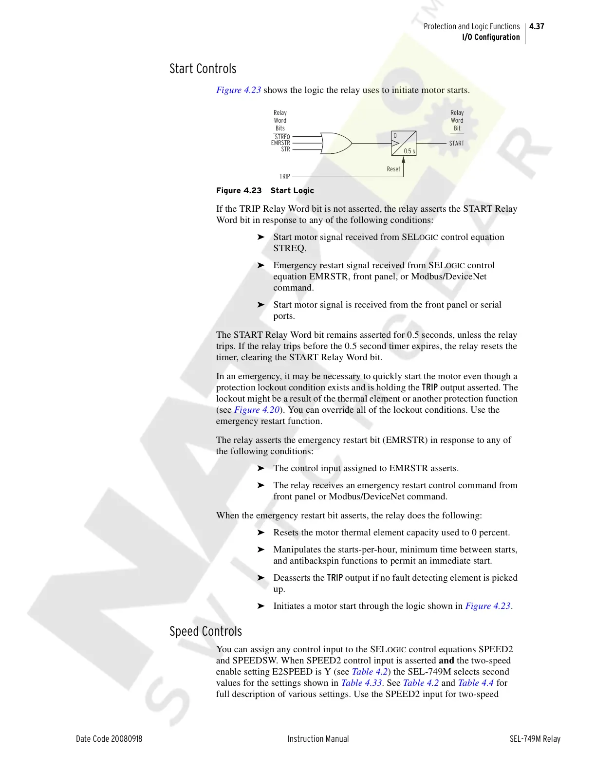
Figure 4.23 shows the logic the relay uses to initiate motor starts.
Figure 4.23 Start Logic
If the TRIP Relay Word bit is not asserted, the relay asserts the START Relay
Word bit in response to any of the following conditions:
➤ Start motor signal received from SELOGIC control equation
STREQ.
➤ Emergency restart signal received from SELOGIC control
equation EMRSTR, front panel, or Modbus/DeviceNet
command.
➤ Start motor signal is received from the front panel or serial
ports.
The START Relay Word bit remains asserted for 0.5 seconds, unless the relay
trips. If the relay trips before the 0.5 second timer expires, the relay resets the
timer, clearing the START Relay Word bit.
In an emergency, it may be necessary to quickly start the motor even though a
protection lockout condition exists and is holding the TRIP output asserted. The
lockout might be a result of the thermal element or another protection function
(see Figure 4.20). You can override all of the lockout conditions. Use the
emergency restart function.
The relay asserts the emergency restart bit (EMRSTR) in response to any of
the following conditions:
➤ The control input assigned to EMRSTR asserts.
➤ The relay receives an emergency restart control command from
front panel or Modbus/DeviceNet command.
When the emergency restart bit asserts, the relay does the following:
➤ Resets the motor thermal element capacity used to 0 percent.
➤ Manipulates the starts-per-hour, minimum time between starts,
and antibackspin functions to permit an immediate start.
➤ Deasserts the TRIP output if no fault detecting element is picked
up.
➤ Initiates a motor start through the logic shown in Figure 4.23.
Speed Controls
You can assign any control input to the SELOGIC control equations SPEED2
and SPEEDSW. When SPEED2 control input is asserted and the two-speed
enable setting E2SPEED is Y (see Table 4.2) the SEL-749M selects second
values for the settings shown in Table 4.33. See Table 4.2 and Table 4.4 for
full description of various settings. Use the SPEED2 input for two-speed
TRIP
Reset
START
STREQ
EMRSTR
STR
0
0.5 s
Relay
Word
Bit
Relay
Word
Bits
Courtesy of NationalSwitchgear.com