4.8
SEL-749M Relay Instruction Manual Date Code 20080918
Protection and Logic Functions
Basic Motor Protection
Phase current transformers having 150:5 ratios are selected for the
application. The SEL-749M settings for the application are shown
below.
Current Transformer Ratio (CTR) = 150/5 = 30
Full Load Amps (FLA) = 101 A primary
Service Factor (SF) = 1.15
Curve Number (CURVE) = 14
See Example 4.3 for the equation to calculate the RTC, use
TD = 1
LRA = 6
LRTHOT = Curve# • 2.08
RTC = 81 minutes
COOLTIME = 243 minutes
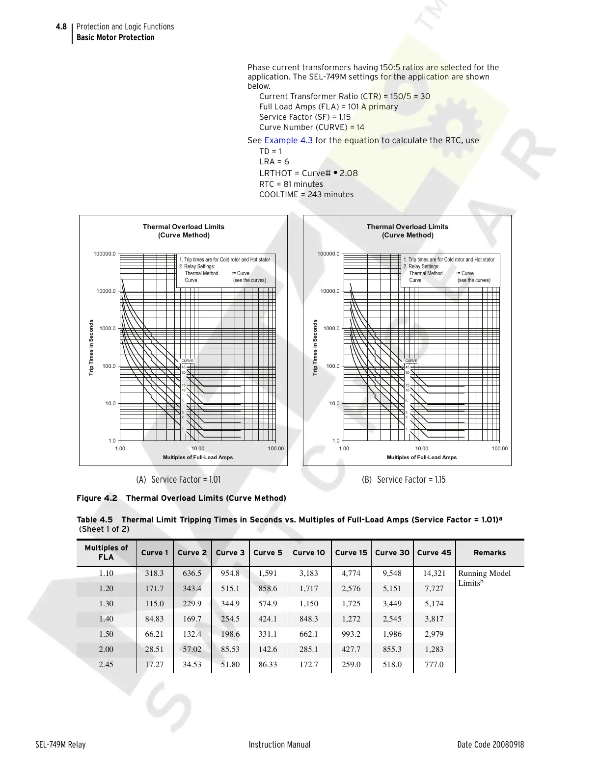
Figure 4.2 Thermal Overload Limits (Curve Method)
Thermal Overload Limits
(Curve Method)
1.0
10.0
100.0
1000.0
10000.0
100000.0
1.00 10.00 100.00
Multiples of Full-Load Amps
Trip Times in Seconds
45
30
15
10
5
3
2
1
CURV E
Thermal Overload Limits
(Curve Method)
1.0
10.0
100.0
1000.0
10000.0
100000.0
1.00 10.00 100.00
Multiples of Full-Load Amps
Trip Times in Seconds
45
30
15
10
5
3
2
1
CURV E
(A) Service Factor = 1.01 (B) Service Factor = 1.15
1. Trip times are for Cold rotor and Hot stator
2. Relay Settings:
Thermal Method := Curve
Curve (see the curves)
1. Trip times are for Cold rotor and Hot stator
2. Relay Settings:
Thermal Method := Curve
Curve (see the curves)
Table 4.5 Thermal Limit Tripping Times in Seconds vs. Multiples of Full-Load Amps (Service Factor = 1.01)
a
(Sheet 1 of 2)
Multiples of
FLA
Curve 1 Curve 2 Curve 3 Curve 5 Curve 10 Curve 15 Curve 30 Curve 45 Remarks
1.10 318.3 636.5 954.8 1,591 3,183 4,774 9,548 14,321 Running Model
Limits
b
1.20 171.7 343.4 515.1 858.6 1,717 2,576 5,151 7,727
1.30 115.0 229.9 344.9 574.9 1,150 1,725 3,449 5,174
1.40 84.83 169.7 254.5 424.1 848.3 1,272 2,545 3,817
1.50 66.21 132.4 198.6 331.1 662.1 993.2 1,986 2,979
2.00 28.51 57.02 85.53 142.6 285.1 427.7 855.3 1,283
2.45 17.27 34.53 51.80 86.33 172.7 259.0 518.0 777.0
Courtesy of NationalSwitchgear.com