4.51
Date Code 20080918 Instruction Manual SEL-749M Relay
Protection and Logic Functions
Logic Functions
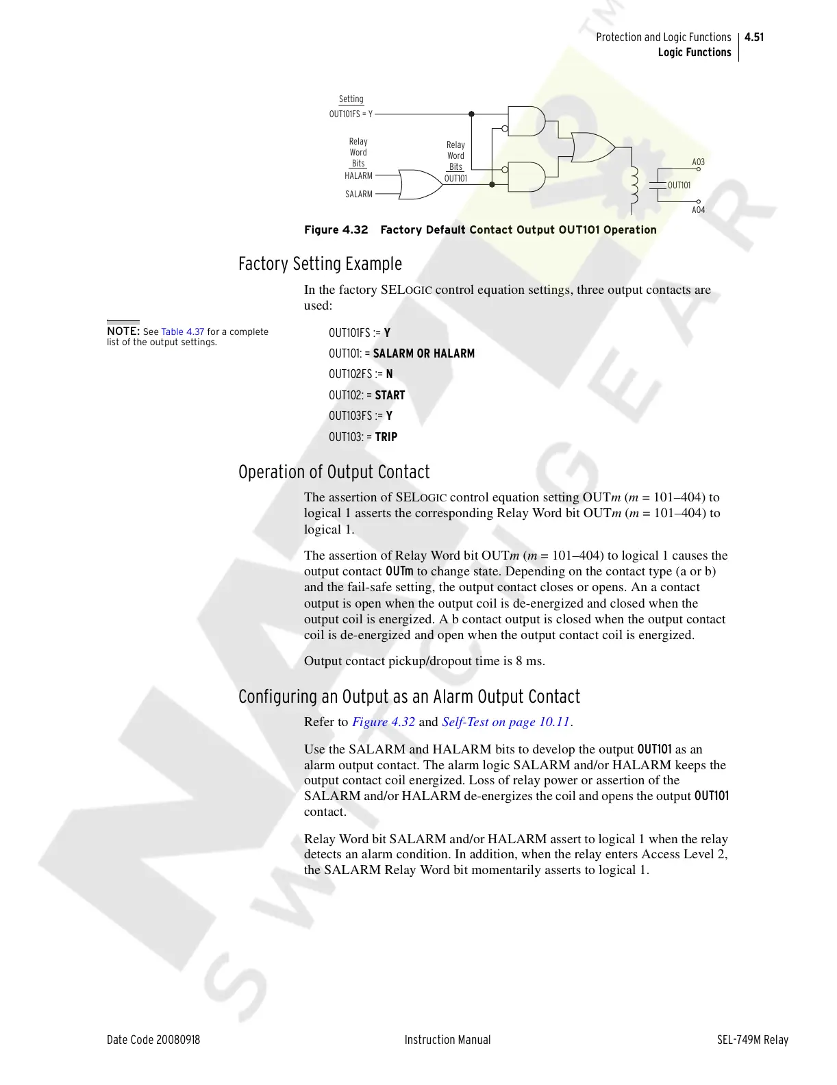
Figure 4.32 Factory Default Contact Output OUT101 Operation
Factory Setting Example
In the factory SELOGIC control equation settings, three output contacts are
used:
NOTE: See Tab le 4. 37 for a complete
list of the output settings.
OUT101FS := Y
OUT101: = SALARM OR HALARM
OUT102FS := N
OUT102: = START
OUT103FS := Y
OUT103: = TRIP
Operation of Output Contact
The assertion of SELOGIC control equation setting OUTm (m = 101–404) to
logical 1 asserts the corresponding Relay Word bit OUTm (m = 101–404) to
logical 1.
The assertion of Relay Word bit OUTm (m = 101–404) to logical 1 causes the
output contact OUTm to change state. Depending on the contact type (a or b)
and the fail-safe setting, the output contact closes or opens. An a contact
output is open when the output coil is de-energized and closed when the
output coil is energized. A b contact output is closed when the output contact
coil is de-energized and open when the output contact coil is energized.
Output contact pickup/dropout time is 8 ms.
Configuring an Output as an Alarm Output Contact
Refer to Figure 4.32 and Self-Test on page 10.11.
Use the SALARM and HALARM bits to develop the output OUT101 as an
alarm output contact. The alarm logic SALARM and/or HALARM keeps the
output contact coil energized. Loss of relay power or assertion of the
SALARM and/or HALARM de-energizes the coil and opens the output OUT101
contact.
Relay Word bit SALARM and/or HALARM assert to logical 1 when the relay
detects an alarm condition. In addition, when the relay enters Access Level 2,
the SALARM Relay Word bit momentarily asserts to logical 1.
OUT101
A03
A04
OUT101FS = Y
HALARM
OUT101
SALARM
Relay
Word
Bits
Relay
Word
Bits
Setting
Courtesy of NationalSwitchgear.com



 To Next Page