4.16
SEL-749M Relay Instruction Manual Date Code 20080918
Protection and Logic Functions
Basic Motor Protection
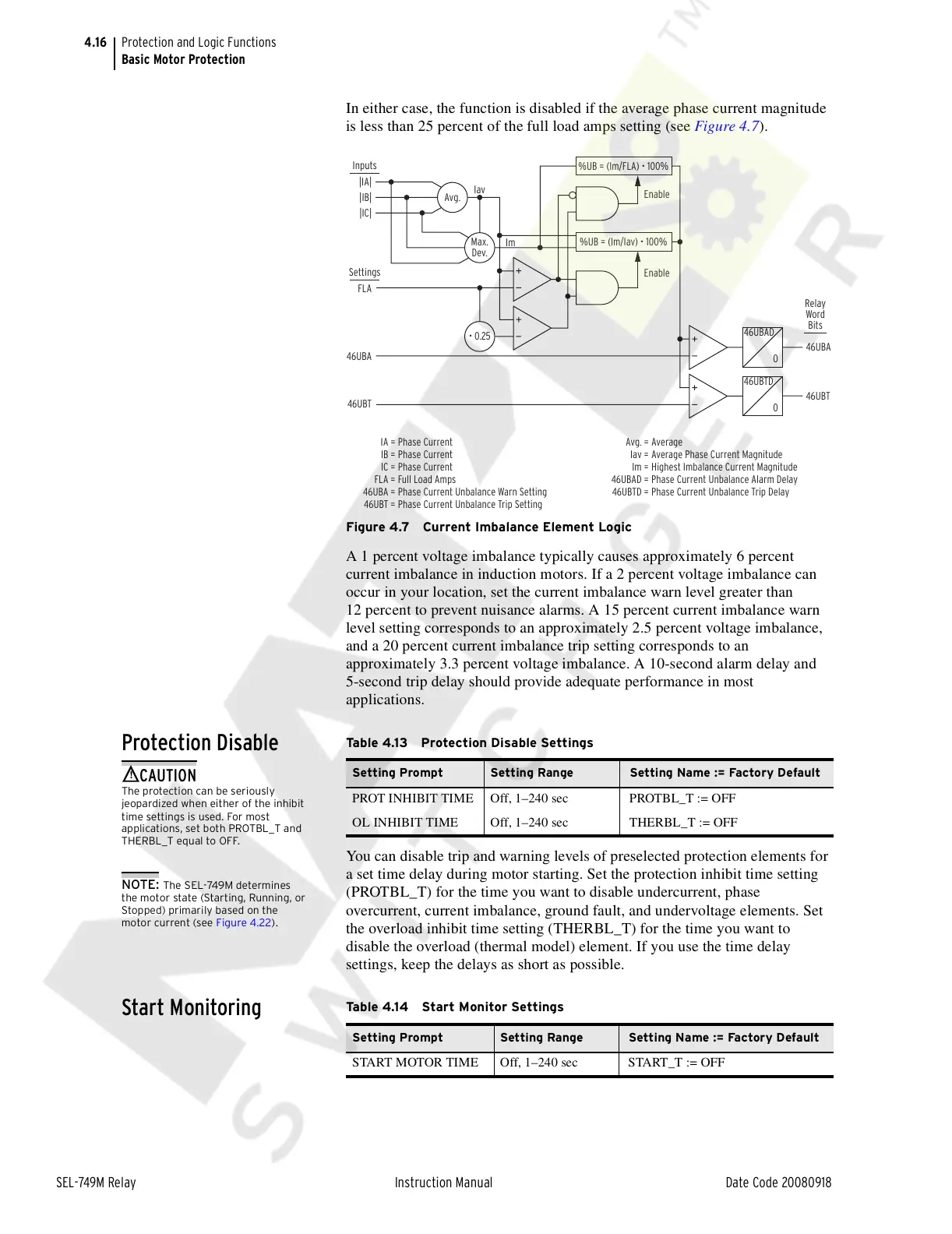
In either case, the function is disabled if the average phase current magnitude
is less than 25 percent of the full load amps setting (see Figure 4.7).
Figure 4.7 Current Imbalance Element Logic
A 1 percent voltage imbalance typically causes approximately 6 percent
current imbalance in induction motors. If a 2 percent voltage imbalance can
occur in your location, set the current imbalance warn level greater than
12 percent to prevent nuisance alarms. A 15 percent current imbalance warn
level setting corresponds to an approximately 2.5 percent voltage imbalance,
and a 20 percent current imbalance trip setting corresponds to an
approximately 3.3 percent voltage imbalance. A 10-second alarm delay and
5-second trip delay should provide adequate performance in most
applications.
Protection Disable
You can disable trip and warning levels of preselected protection elements for
a set time delay during motor starting. Set the protection inhibit time setting
(PROTBL_T) for the time you want to disable undercurrent, phase
overcurrent, current imbalance, ground fault, and undervoltage elements. Set
the overload inhibit time setting (THERBL_T) for the time you want to
disable the overload (thermal model) element. If you use the time delay
settings, keep the delays as short as possible.
Start Monitoring
46UBAD
0
46UBA
46UBTD
0
46UBT
Enable
Enable
Im
Iav
|IA|
|IC|
FLA
46UBA
46UBT
|IB|
Relay
Word
Bits
%UB = (Im/Iav) • 100%
Avg.
• 0.25
Max.
Dev.
Settings
Inputs
%UB = (Im/FLA) • 100%
IA =
IB =
IC =
FLA =
46UBA =
46UBT =
Phase Current
Phase Current
Phase Current
Full Load Amps
Phase Current Unbalance Warn Setting
Phase Current Unbalance Trip Setting
Avg. =
Iav =
Im =
46UBAD =
46UBTD =
Average
Average Phase Current Magnitude
Highest Imbalance Current Magnitude
Phase Current Unbalance Alarm Delay
Phase Current Unbalance Trip Delay
Table 4.13 Protection Disable Settings
Setting Prompt Setting Range Setting Name := Factory Default
PROT INHIBIT TIME Off, 1–240 sec PROTBL_T := OFF
OL INHIBIT TIME Off, 1–240 sec THERBL_T := OFF
!
CAUTION
The protection can be seriously
eopardized when either of the inhibit
time settings is used. For most
applications, set both PROTBL_T and
THERBL_T equal to OFF.
NOTE: The SEL-749M determines
the motor state (Starting, Running, or
Stopped) primarily based on the
motor current (see Figure 4.22).
Table 4.14 Start Monitor Settings
Setting Prompt Setting Range Setting Name := Factory Default
START MOTOR TIME Off, 1–240 sec START_T := OFF
Courtesy of NationalSwitchgear.com