4.47
Date Code 20080918 Instruction Manual SEL-749M Relay
Protection and Logic Functions
Logic Functions
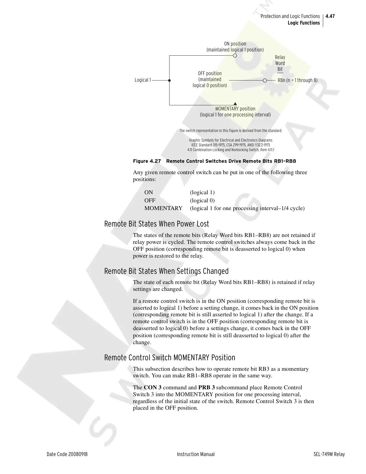
Figure 4.27 Remote Control Switches Drive Remote Bits RB1–RB8
Any given remote control switch can be put in one of the following three
positions:
Remote Bit States When Power Lost
The states of the remote bits (Relay Word bits RB1–RB8) are not retained if
relay power is cycled. The remote control switches always come back in the
OFF position (corresponding remote bit is deasserted to logical 0) when
power is restored to the relay.
Remote Bit States When Settings Changed
The state of each remote bit (Relay Word bits RB1–RB8) is retained if relay
settings are changed.
If a remote control switch is in the ON position (corresponding remote bit is
asserted to logical 1) before a setting change, it comes back in the ON position
(corresponding remote bit is still asserted to logical 1) after the change. If a
remote control switch is in the OFF position (corresponding remote bit is
deasserted to logical 0) before a settings change, it comes back in the OFF
position (corresponding remote bit is still deasserted to logical 0) after the
change.
Remote Control Switch MOMENTARY Position
This subsection describes how to operate remote bit RB3 as a momentary
switch. You can make RB1–RB8 operate in the same way.
The CON 3 command and PRB 3 subcommand place Remote Control
Switch 3 into the MOMENTARY position for one processing interval,
regardless of the initial state of the switch. Remote Control Switch 3 is then
placed in the OFF position.
ON (logical 1)
OFF (logical 0)
MOMENTARY (logical 1 for one processing interval–1/4 cycle)
Logical 1
OFF position
(maintained
logical 0 position)
ON position
(maintained logical 1 position)
MOMENTARY position
(logical 1 for one processing interval)
RBn (n = 1 through 8)
Relay
Word
Bit
The switch representation in this figure is derived from the standard:
Graphic Symbols for Electrical and Electronics Diagrams
IEEE Standard 315-1975, CSA Z99-1975, ANSI Y32.2-1975
4.11 Combination Locking and Nonlocking Switch, Item 4.11.1
Courtesy of NationalSwitchgear.com