4.9
Date Code 20080918 Instruction Manual SEL-749M Relay
Protection and Logic Functions
Basic Motor Protection
Additional Thermal
Overload Settings
When the motor thermal capacity used exceeds the overload warning level
setting (TCAPU), the relay issues a warning (the Relay Word bit 49A asserts).
The early warning may allow you to correct the load problem before a thermal
trip occurs. Set TCAPU using the following criteria to avoid nuisance
overload warnings when running the motor at full load:
Equation 4.1
The motor tripping and starting functions include supervision to help prevent a
thermal trip on a normal start. The relay prevents motor starting until the
thermal element has enough available starting thermal capacity to allow a
motor start without tripping. The available thermal capacity required to start is
(100–TCSTART), where TCSTART is the start inhibit level setting. This
feature can be disabled by setting TCSTART equal to OFF.
Equation 4.2
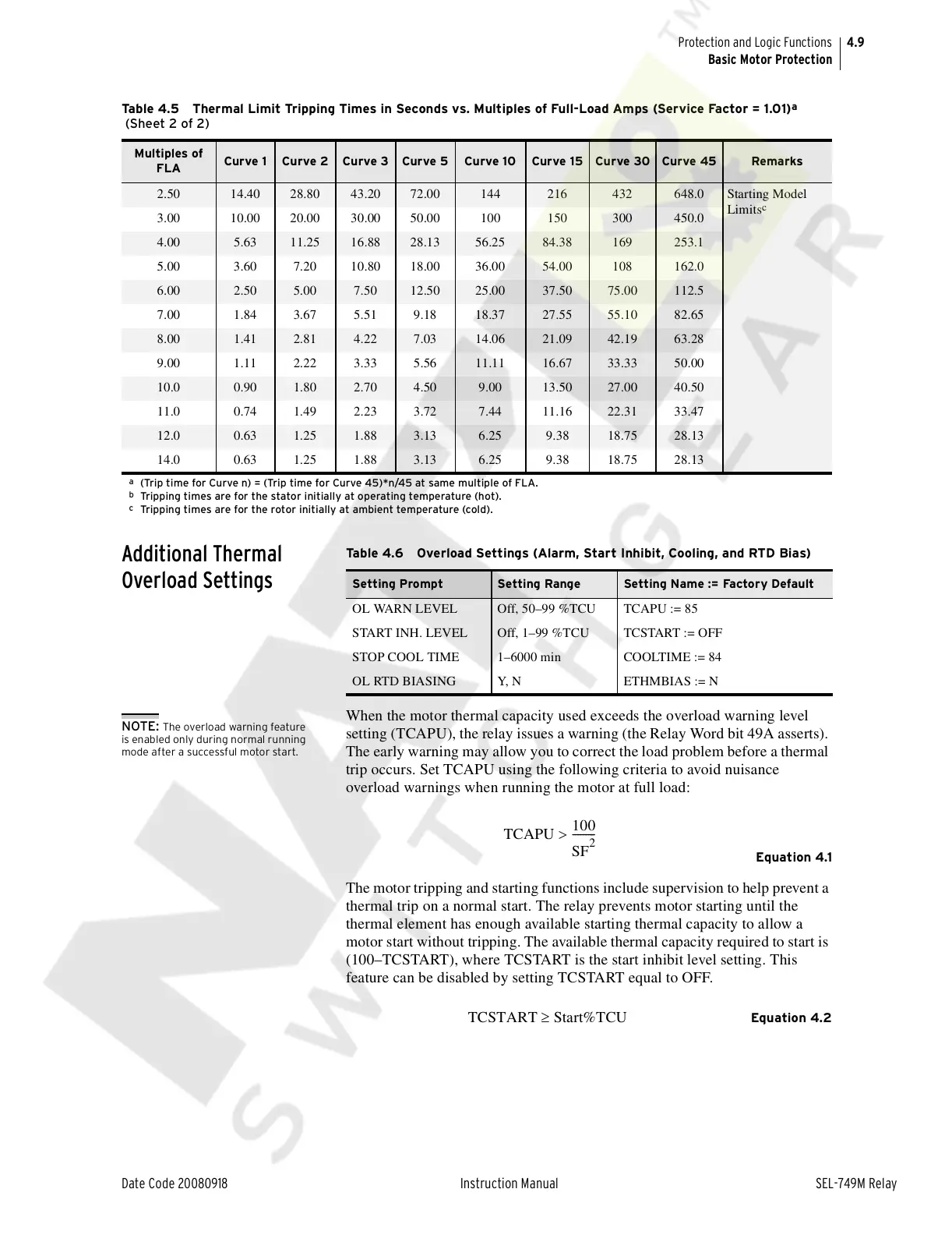
2.50 14.40 28.80 43.20 72.00 144 216 432 648.0 Starting Model
Limits
c
3.00 10.00 20.00 30.00 50.00 100 150 300 450.0
4.00 5.63 11.25 16.88 28.13 56.25 84.38 169 253.1
5.00 3.60 7.20 10.80 18.00 36.00 54.00 108 162.0
6.00 2.50 5.00 7.50 12.50 25.00 37.50 75.00 112.5
7.00 1.84 3.67 5.51 9.18 18.37 27.55 55.10 82.65
8.00 1.41 2.81 4.22 7.03 14.06 21.09 42.19 63.28
9.00 1.11 2.22 3.33 5.56 11.11 16.67 33.33 50.00
10.0 0.90 1.80 2.70 4.50 9.00 13.50 27.00 40.50
11.0 0.74 1.49 2.23 3.72 7.44 11.16 22.31 33.47
12.0 0.63 1.25 1.88 3.13 6.25 9.38 18.75 28.13
14.0 0.63 1.25 1.88 3.13 6.25 9.38 18.75 28.13
a
(Trip time for Curve n) = (Trip time for Curve 45)*n/45 at same multiple of FLA.
b
Tripping times are for the stator initially at operating temperature (hot).
c
Tripping times are for the rotor initially at ambient temperature (cold).
Table 4.5 Thermal Limit Tripping Times in Seconds vs. Multiples of Full-Load Amps (Service Factor = 1.01)
a
(Sheet 2 of 2)
Multiples of
FLA
Curve 1 Curve 2 Curve 3 Curve 5 Curve 10 Curve 15 Curve 30 Curve 45 Remarks
Table 4.6 Overload Settings (Alarm, Start Inhibit, Cooling, and RTD Bias)
Setting Prompt Setting Range Setting Name := Factory Default
OL WARN LEVEL Off, 50–99 %TCU TCAPU := 85
START INH. LEVEL Off, 1–99 %TCU TCSTART := OFF
STOP COOL TIME 1–6000 min COOLTIME := 84
OL RTD BIASING Y, N ETHMBIAS := N
NOTE: The overload warning feature
is enabled only during normal running
mode after a successful motor start.
TCAPU
100
SF
2
---------
>
TCSTART Start%TCU≥
Courtesy of NationalSwitchgear.com