2.8
SEL-749M Relay Instruction Manual Date Code 20080918
Installation
Rear-Panel Connections
Rear-Panel and Top-
Panel Diagrams
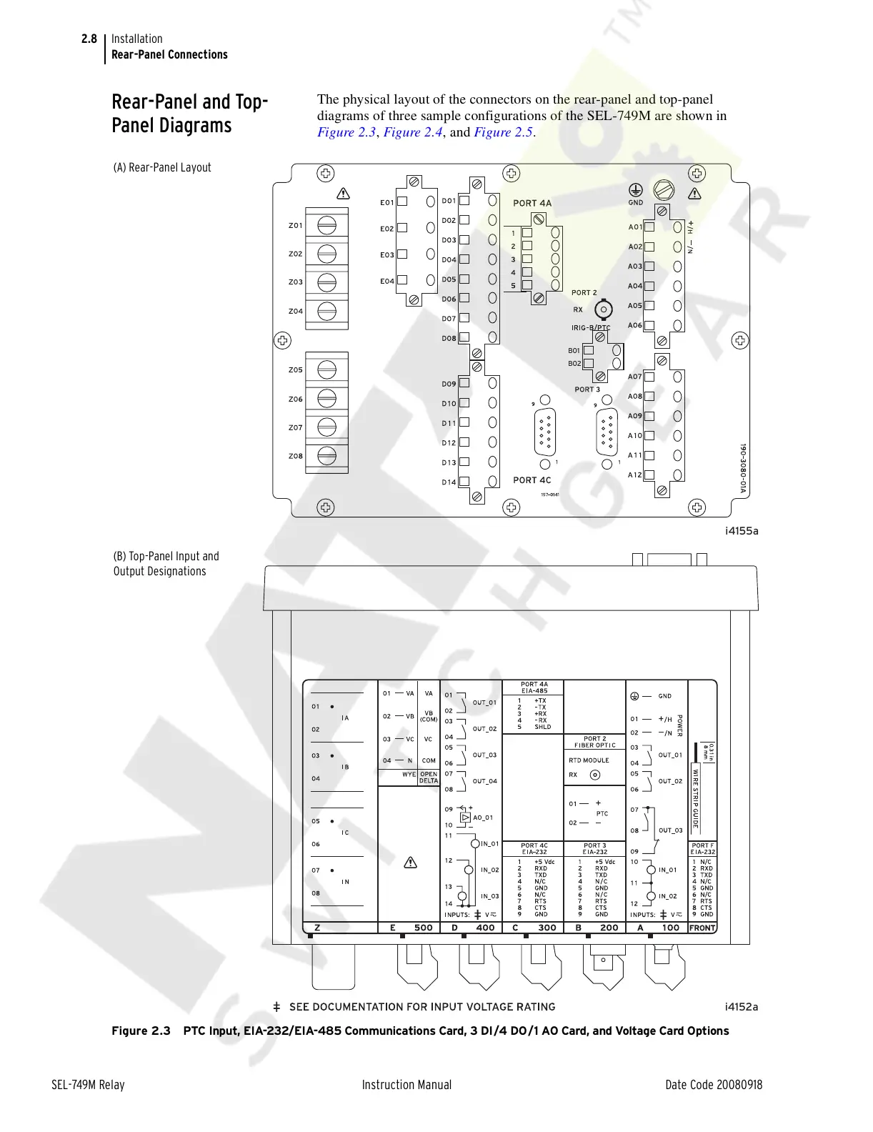
The physical layout of the connectors on the rear-panel and top-panel
diagrams of three sample configurations of the SEL-749M are shown in
Figure 2.3, Figure 2.4, and Figure 2.5.
Figure 2.3 PTC Input, EIA-232/EIA-485 Communications Card, 3 DI/4 DO /1 AO Card, and Voltage Card Options
i4155a
B01
B02
i4152a
(A) Rear-Panel Layout
(B) Top-Panel Input and
Output Designations
Courtesy of NationalSwitchgear.com