4.39
Date Code 20080918 Instruction Manual SEL-749M Relay
Protection and Logic Functions
Logic Settings (SET L Command)
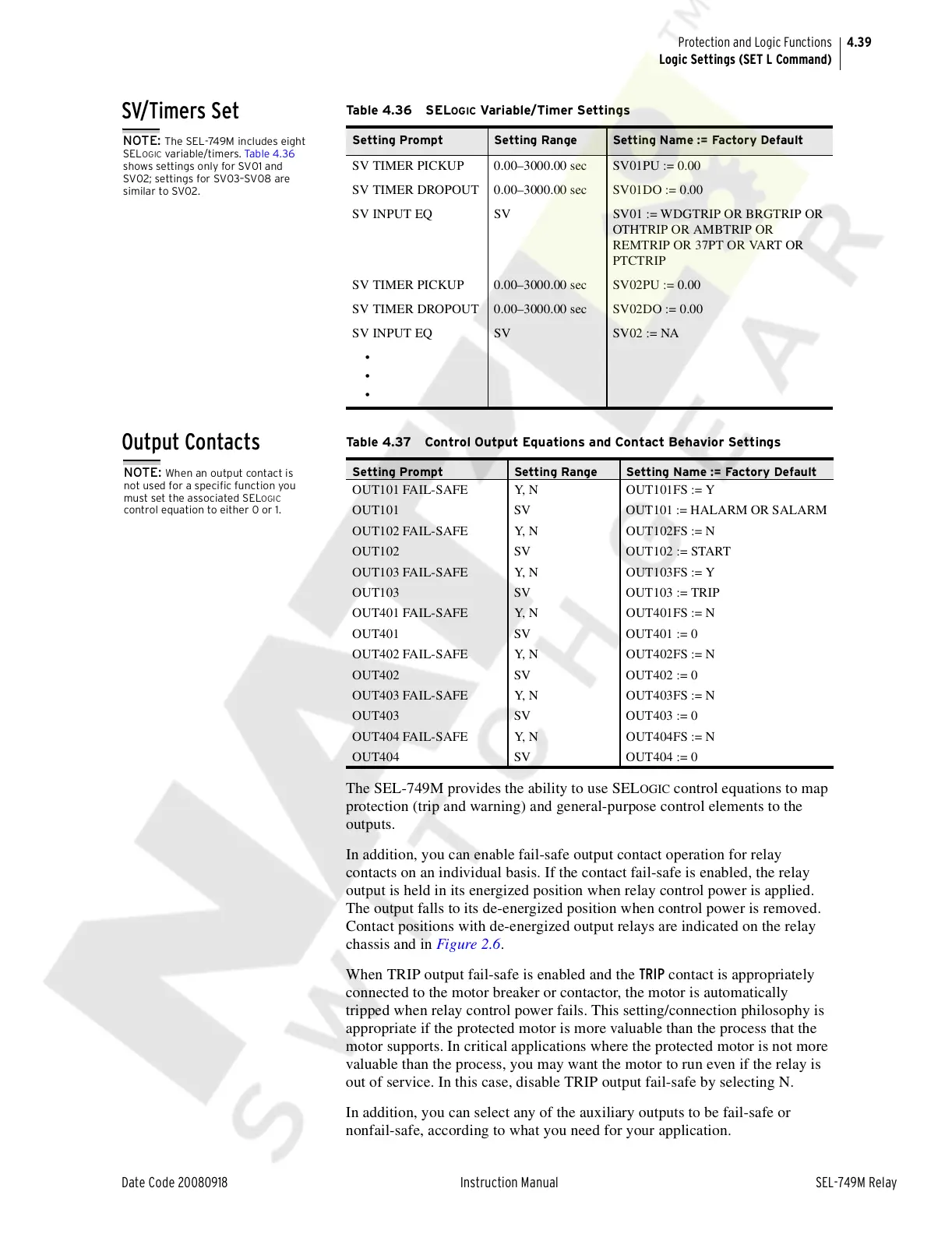
SV/Timers Set
Output Contacts
The SEL-749M provides the ability to use SELOGIC control equations to map
protection (trip and warning) and general-purpose control elements to the
outputs.
In addition, you can enable fail-safe output contact operation for relay
contacts on an individual basis. If the contact fail-safe is enabled, the relay
output is held in its energized position when relay control power is applied.
The output falls to its de-energized position when control power is removed.
Contact positions with de-energized output relays are indicated on the relay
chassis and in Figure 2.6.
When TRIP output fail-safe is enabled and the TRIP contact is appropriately
connected to the motor breaker or contactor, the motor is automatically
tripped when relay control power fails. This setting/connection philosophy is
appropriate if the protected motor is more valuable than the process that the
motor supports. In critical applications where the protected motor is not more
valuable than the process, you may want the motor to run even if the relay is
out of service. In this case, disable TRIP output fail-safe by selecting N.
In addition, you can select any of the auxiliary outputs to be fail-safe or
nonfail-safe, according to what you need for your application.
NOTE: The SEL-749M includes eight
SEL
OGIC variable/timers. Tab le 4 .3 6
shows settings only for SV01 and
SV02; settings for SV03–SV08 are
similar to SV02.
Ta b l e 4 . 36 S ELOGIC Variable/Timer Settings
Setting Prompt Setting Range Setting Name := Factory Default
SV TIMER PICKUP 0.00–3000.00 sec SV01PU := 0.00
SV TIMER DROPOUT 0.00–3000.00 sec SV01DO := 0.00
SV INPUT EQ SV SV01 := WDGTRIP OR BRGTRIP OR
OTHTRIP OR AMBTRIP OR
REMTRIP OR 37PT OR VART OR
PTCTRIP
SV TIMER PICKUP 0.00–3000.00 sec SV02PU := 0.00
SV TIMER DROPOUT 0.00–3000.00 sec SV02DO := 0.00
SV INPUT EQ SV SV02 := NA
•
•
•
NOTE: When an output contact is
not used for a specific function you
must set the associated SEL
OGIC
control equation to either 0 or 1.
Table 4.37 Control Output Equations and Contact Behavior Settings
Setting Prompt Setting Range Setting Name := Factory Default
OUT101 FAIL-SAFE Y, N OUT101FS := Y
OUT101 SV OUT101 := HALARM OR SALARM
OUT102 FAIL-SAFE Y, N OUT102FS := N
OUT102 SV OUT102 := START
OUT103 FAIL-SAFE Y, N OUT103FS := Y
OUT103 SV OUT103 := TRIP
OUT401 FAIL-SAFE Y, N OUT401FS := N
OUT401 SV OUT401 := 0
OUT402 FAIL-SAFE Y, N OUT402FS := N
OUT402 SV OUT402 := 0
OUT403 FAIL-SAFE Y, N OUT403FS := N
OUT403 SV OUT403 := 0
OUT404 FAIL-SAFE Y, N OUT404FS := N
OUT404 SV OUT404 := 0
Courtesy of NationalSwitchgear.com


 To Next Page