2.13
Date Code 20080918 Instruction Manual SEL-749M Relay
Installation
AC/DC Control Connection Diagrams
Wire Sizes and
Insulation
Wire sizes for grounding (earthing), current, voltage, and contact connections
are dictated by the terminal blocks and expected load currents. You may use
Figure 2.9 as a guide in selecting wire sizes:
You should use wire with 0.4 mm thick insulation for high-voltage
connections to allow for contact between adjacent wires. If possible, use
0.4 mm insulated wires for all connections.
AC/DC Control Connection Diagrams
This section describes fail-safe versus nonfail-safe tripping, describes voltage
connections, and provides the ac and dc wiring diagrams for the following
applications:
➤ Across the line starting
➤ Star-delta starting
➤ Two-speed motor
Fail-Safe/Nonfail-Safe
Tripping
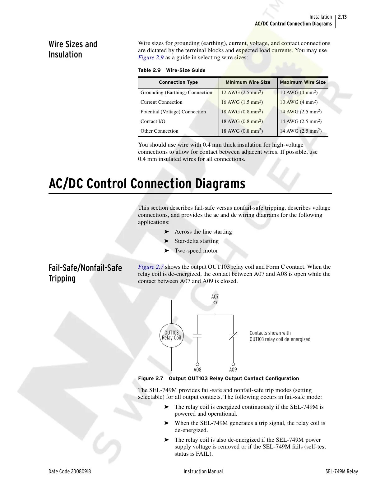
Figure 2.7 shows the output OUT103 relay coil and Form C contact. When the
relay coil is de-energized, the contact between A07 and A08 is open while the
contact between A07 and A09 is closed.
Figure 2.7 Output OUT103 Relay Output Contact Configuration
The SEL-749M provides fail-safe and nonfail-safe trip modes (setting
selectable) for all output contacts. The following occurs in fail-safe mode:
➤ The relay coil is energized continuously if the SEL-749M is
powered and operational.
➤ When the SEL-749M generates a trip signal, the relay coil is
de-energized.
➤ The relay coil is also de-energized if the SEL-749M power
supply voltage is removed or if the SEL-749M fails (self-test
status is FAIL).
Table 2.9 Wire-Size Guide
Connection Type Minimum Wire Size Maximum Wire Size
Grounding (Earthing) Connection 12 AWG (2.5 mm
2
)10 AWG (4 mm
2
)
Current Connection 16 AWG (1.5 mm
2
)10 AWG (4 mm
2
)
Potential (Voltage) Connection 18 AWG (0.8 mm
2
) 14 AWG (2.5 mm
2
)
Contact I/O 18 AWG (0.8 mm
2
) 14 AWG (2.5 mm
2
)
Other Connection 18 AWG (0.8 mm
2
) 14 AWG (2.5 mm
2
)
A07
A08 A09
Contacts shown with
OUT103 relay coil de-energized
OUT103
Relay Coil
Courtesy of NationalSwitchgear.com