4.46
SEL-749M Relay Instruction Manual Date Code 20080918
Protection and Logic Functions
Logic Functions
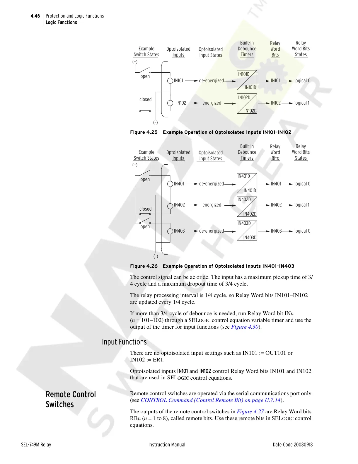
Figure 4.25 Example Operation of Optoisolated Inputs IN101–IN102
Figure 4.26 Example Operation of Optoisolated Inputs IN401–IN403
The control signal can be ac or dc. The input has a maximum pickup time of 3/
4 cycle and a maximum dropout time of 3/4 cycle.
The relay processing interval is 1/4 cycle, so Relay Word bits IN101–IN102
are updated every 1/4 cycle.
If more than 3/4 cycle of debounce is needed, run Relay Word bit INn
(n = 101–102) through a SEL
OGIC control equation variable timer and use the
output of the timer for input functions (see Figure 4.30).
Input Functions
There are no optoisolated input settings such as IN101 := OUT101 or
IN102 := ER1.
Optoisolated inputs IN101 and IN102 control Relay Word bits IN101 and IN102
that are used in SEL
OGIC control equations.
Remote Control
Switches
Remote control switches are operated via the serial communications port only
(see CONTROL Command (Control Remote Bit) on page U.7.14).
The outputs of the remote control switches in Figure 4.27 are Relay Word bits
RBn (n = 1 to 8), called remote bits. Use these remote bits in SEL
OGIC control
equations.
open
closed
Example
Switch States
Optoisolated
Input States
Optoisolated
Inputs
Built-In
Debounce
Timers
Relay
Word
Bits
Relay
Word Bits
States
IN101 de-energized IN101 logical 0
energizedIN102 IN102 logical 1
(+)
(–)
IN101D
IN101D
IN102D
IN102D
Example
Switch States
Optoisolated
Input States
Optoisolated
Inputs
Built-In
Debounce
Timers
Relay
Word
Bits
Relay
Word Bits
States
open
closed
IN401 de-energized IN401 logical 0
energizedIN402 IN402 logical 1
(+)
IN401D
IN401D
IN402D
IN402D
open
IN403 de-energized IN403 logical 0
(–)
IN403D
IN403D
Courtesy of NationalSwitchgear.com