C.7
Date Code 20080918 Instruction Manual SEL-749M Relay
SEL Communications Processors
SEL Communications Processor Example
SEL Communications Processor Example
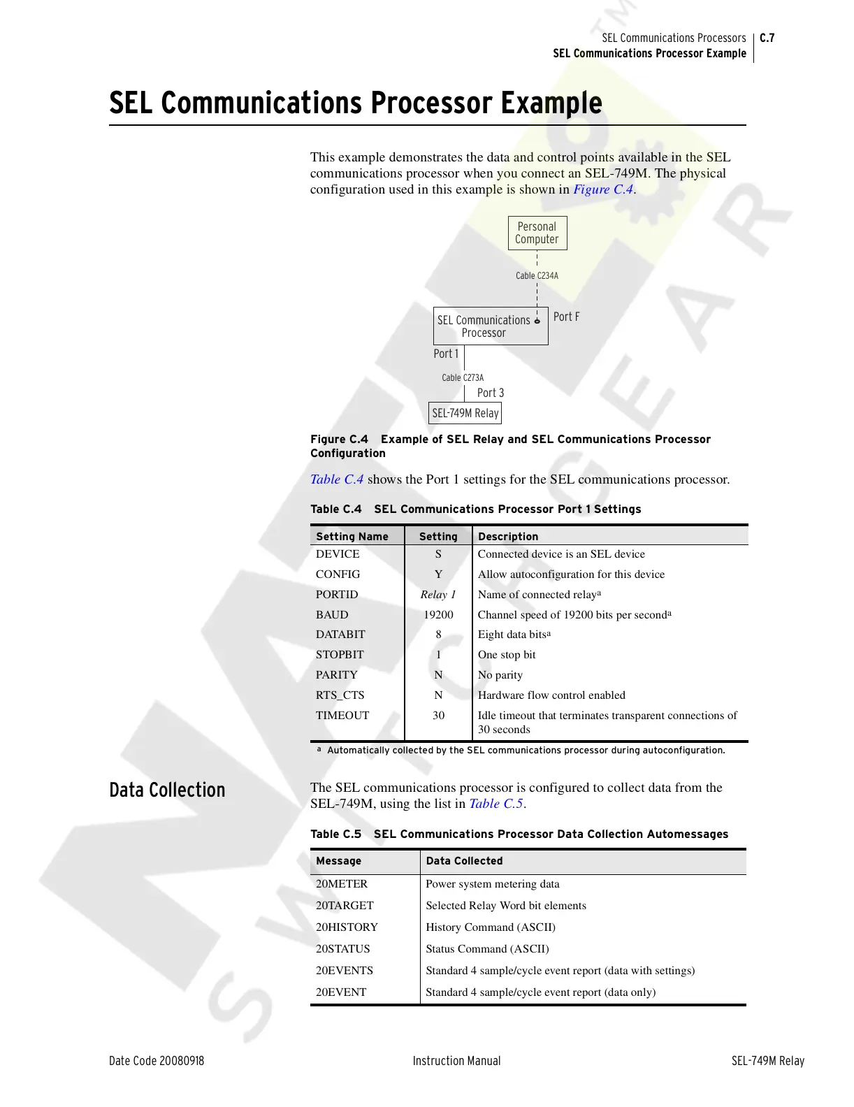
This example demonstrates the data and control points available in the SEL
communications processor when you connect an SEL-749M. The physical
configuration used in this example is shown in Figure C.4.
Figure C.4 Example of SEL Relay and SEL Communications Processor
Configuration
Table C.4 shows the Port 1 settings for the SEL communications processor.
Data Collection
The SEL communications processor is configured to collect data from the
SEL-749M, using the list in Table C.5.
Table C.4 SEL Communications Processor Port 1 Settings
Setting Name Setting Description
DEVICE S Connected device is an SEL device
CONFIG Y Allow autoconfiguration for this device
PORTID Relay 1 Name of connected relay
a
a
Automatically collected by the SEL communications processor during autoconfiguration.
BAUD 19200 Channel speed of 19200 bits per second
a
DATABIT 8 Eight data bits
a
STOPBIT 1 One stop bit
PARITY N No parity
RTS_CTS N Hardware flow control enabled
TIMEOUT 30 Idle timeout that terminates transparent connections of
30 seconds
SEL Communications
Processor
SEL-749M Relay
Personal
Computer
Port F
Port 1
Port 3
Cable C273A
Cable C234A
Table C.5 SEL Communications Processor Data Collection Automessages
Message Data Collected
20METER Power system metering data
20TARGET Selected Relay Word bit elements
20HISTORY History Command (ASCII)
20STATUS Status Command (ASCII)
20EVENTS Standard 4 sample/cycle event report (data with settings)
20EVENT Standard 4 sample/cycle event report (data only)
Courtesy of NationalSwitchgear.com