2.16
SEL-749M Relay Instruction Manual Date Code 20080918
Installation
AC/DC Control Connection Diagrams
Across the
Line Starting
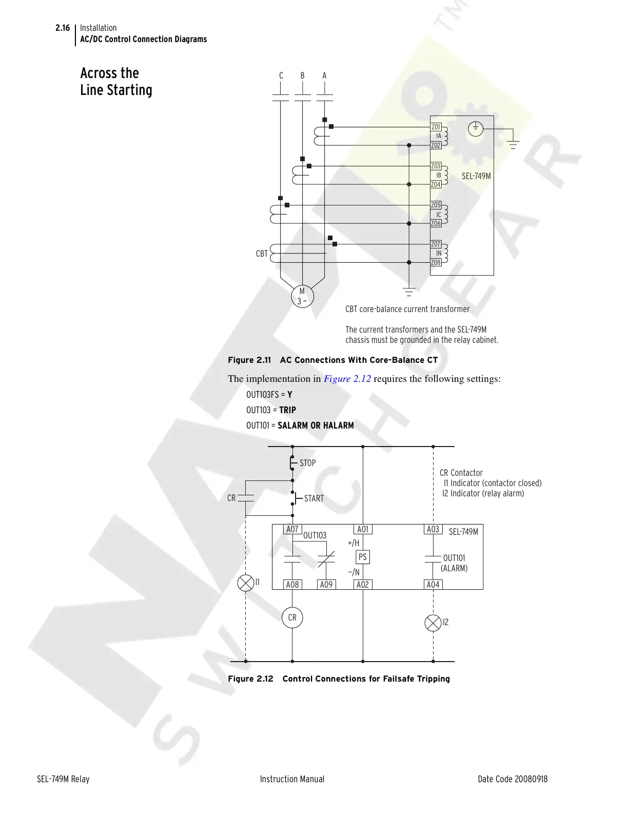
Figure 2.11 AC Connections With Core-Balance CT
The implementation in Figure 2.12 requires the following settings:
OUT103FS = Y
OUT103 = TRIP
OUT101 = SALARM OR HALARM
Figure 2.12 Control Connections for Failsafe Tripping
SEL-749M
CBT
CBT core-balance current transformer
The current transformers and the SEL-749M
chassis must be grounded in the relay cabinet.
ABC
IN
IC
IB
IA
M
3 ~
Z08
Z07
Z06
Z05
Z04
Z03
Z02
Z01
Contactor
Indicator (contactor closed)
Indicator (relay alarm)
CR
I1
I2
R
STOP
START
I1
OUT103
SEL-749M
OUT101
(ALARM)
+/H
—/N
PS
A07 A01 A03
A08
CR
A09 A02 A04
I2
Courtesy of NationalSwitchgear.com