10.5
Date Code 20080918 Instruction Manual SEL-749M Relay
Testing and Troubleshooting
Commissioning Tests
Step 16. Verify that the relay is measuring the magnitude and phase
angle correctly.
The expected magnitude is (applied phase current) • (CTRN).
The expected phase angle is zero (0).
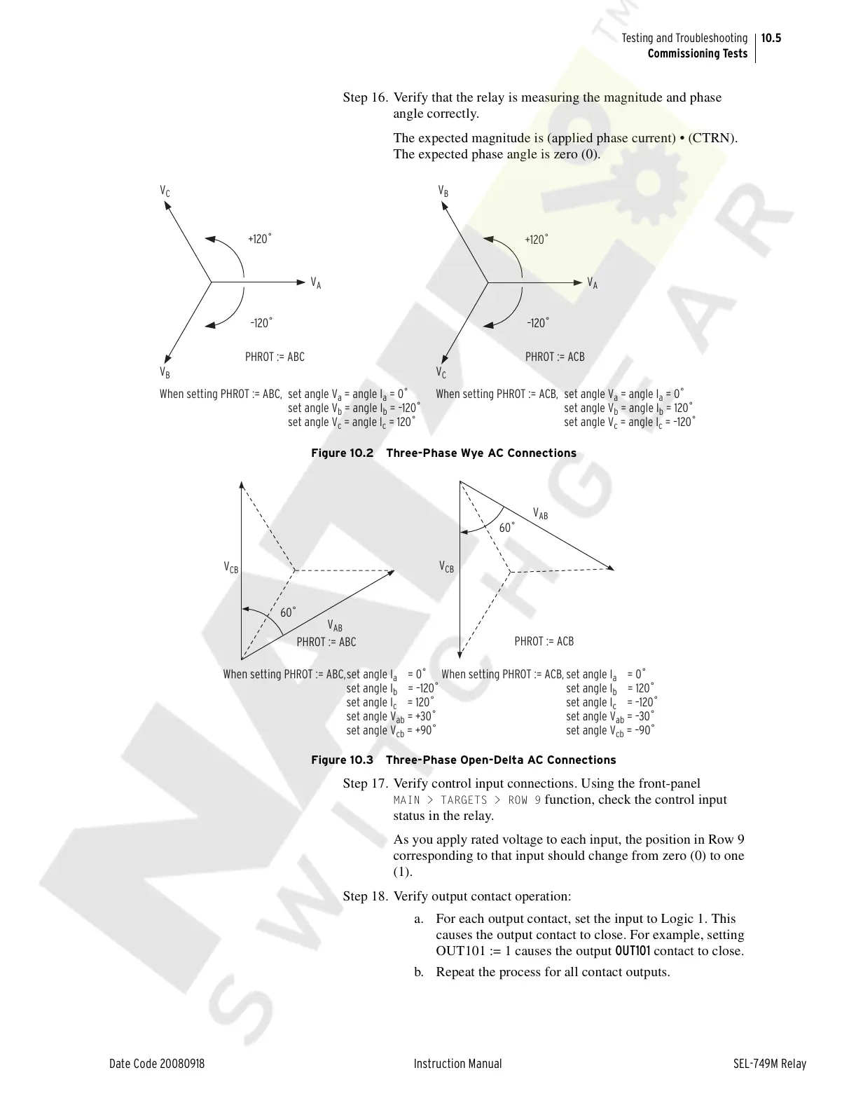
Figure 10.2 Three-Phase Wye AC Connections
Figure 10.3 Three-Phase Open-Delta AC Connections
Step 17. Verify control input connections. Using the front-panel
MAIN > TARGETS > ROW 9 function, check the control input
status in the relay.
As you apply rated voltage to each input, the position in Row 9
corresponding to that input should change from zero (0) to one
(1).
Step 18. Verify output contact operation:
a. For each output contact, set the input to Logic 1. This
causes the output contact to close. For example, setting
OUT101 := 1 causes the output OUT101 contact to close.
b. Repeat the process for all contact outputs.
V
C
+120˚
–120˚
PHROT := ACB
V
B
V
A
+120˚
–120˚
V
C
V
B
V
A
PHROT := ABC
When setting PHROT := ABC, set angle V
a
= angle I
a
= 0˚
set angle V
b
= angle I
b
= –120˚
set angle V
c
= angle I
c
= 120˚
set angle V
a
= angle I
a
= 0˚
set angle V
b
= angle I
b
= 120˚
set angle V
c
= angle I
c
= –120˚
When setting PHROT := ACB,
60˚
V
AB
V
CB
PHROT := ABC
60˚
V
AB
V
CB
PHROT := ACB
When setting PHROT := ABC,set angle I
a
= 0˚
set angle I
b
= –120˚
set angle I
c
= 120˚
set angle V
ab
= +30˚
set angle V
cb
= +90˚
set angle I
a
= 0˚
set angle I
b
= 120˚
set angle I
c
= –120˚
set angle V
ab
= –30˚
set angle V
cb
= –90˚
When setting PHROT := ACB,
Courtesy of NationalSwitchgear.com